
User's Manual
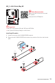
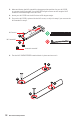
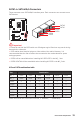
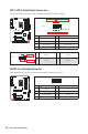
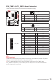
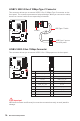
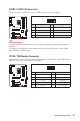
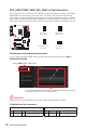
Table Of Contents
- Quick Start
- Specifications
- Package contents
- Block Diagram
- Rear I/O Panel
- Overview of Components
- CPU Socket
- DIMM Slots
- PCI_E1~5: PCIe Expansion Slots
- M2_1~2: M.2 Slots (Key M)
- SATA1~6: SATA 6Gb/s Connectors
- JFP1, JFP2: Front Panel Connectors
- JAUD1: Front Audio Connector
- CPU_PWR1~2, ATX_PWR1: Power Connectors
- JUSBC1: USB 3.2 Gen 2 10Gbps Type-C Connector
- JUSB3: USB 3.2 Gen 1 5Gbps Connector
- JUSB1~2: USB 2.0 Connectors
- JTPM1: TPM Module Connector
- CPU_FAN1, PUMP_FAN1, SYS_FAN1~6: Fan Connectors
- JCI1: Chassis Intrusion Connector
- JCOM1: Serial Port Connector
- JBAT1: Clear CMOS (Reset BIOS) Jumper
- JTBT1: Thunderbolt Add-on Card Connector
- JRTD3: Intel RTD3 Connector
- JRGB1: RGB LED connector
- JRAINBOW1~2: Addressable RGB LED connectors
- JCORSAIR1: CORSAIR Connector
- EZ Debug LED
- LED_SW1: EZ LED Control
- Installing OS, Drivers & Utilities
- UEFI BIOS
- RAID Configuration
- Intel® Optane™ Memory Configuration
- Troubleshooting
- CPU_FAN1, PUMP_FAN1, SYS_FAN1~6: Fan Connectors
- CPU_PWR1~2, ATX_PWR1: Power Connectors
- CPU Socket
- DIMM Slots
- JAUD1: Front Audio Connector
- JBAT1: Clear CMOS (Reset BIOS) Jumper
- JCI1: Chassis Intrusion Connector
- JCOM1: Serial Port Connector
- JCORSAIR1: CORSAIR Connector
- JFP1, JFP2: Front Panel Connectors
- JRAINBOW1~2: Addressable RGB LED connectors
- JRGB1: RGB LED connector
- JRTD3: Intel RTD3 Connector
- JTBT1: Thunderbolt Add-on Card Connector
- JTPM1: TPM Module Connector
- JUSB1~2: USB 2.0 Connectors
- JUSB3: USB 3.2 Gen1 Connector
- JUSBC1: USB 3.2 Gen 2 Type-C Connector
- LED_SW1: EZ LED Control
- M2_1~2: M.2 Slots (Key M)
- PCI_E1~5: PCIe Expansion Slots
- SATA1~6: SATA 6Gb/s Connectors
32
Overview of Components
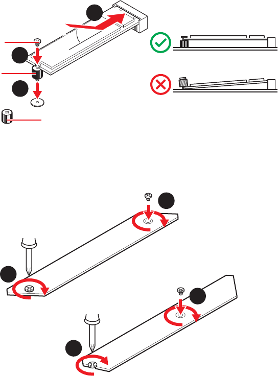
3. Move and fasten the M.2 standoff to the appropriate position for your M.2 SSD,
or remove the M.2 standoff if your M.2 SSD length is same as the length of M.2
heatsink to avoid damage to the M.2 SSD.
4. Insert your M.2 SSD into the M.2 slot at a 30-degree angle.
5. Secure the M.2 SSD in place with the M.2 screw, or skip this step if you remove the
M.2 standoff in step 3.
6. Put the M.2 SHIELD FROZR heatsink back in place and secure it.
6
30º30º
M.2 standoff
heatsink standoff
3
5
4
M.2 screw
6
6
6