
User's Manual
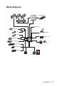
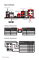
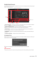
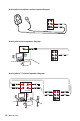
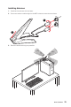
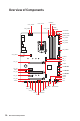
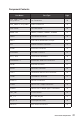
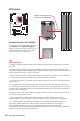
Table Of Contents
- Quick Start
- Specifications
- Package contents
- Block Diagram
- Rear I/O Panel
- Overview of Components
- CPU Socket
- DIMM Slots
- PCI_E1~5: PCIe Expansion Slots
- M2_1~2: M.2 Slots (Key M)
- SATA1~6: SATA 6Gb/s Connectors
- JFP1, JFP2: Front Panel Connectors
- JAUD1: Front Audio Connector
- CPU_PWR1~2, ATX_PWR1: Power Connectors
- JUSBC1: USB 3.2 Gen 2 10Gbps Type-C Connector
- JUSB3: USB 3.2 Gen 1 5Gbps Connector
- JUSB1~2: USB 2.0 Connectors
- JTPM1: TPM Module Connector
- CPU_FAN1, PUMP_FAN1, SYS_FAN1~6: Fan Connectors
- JCI1: Chassis Intrusion Connector
- JCOM1: Serial Port Connector
- JBAT1: Clear CMOS (Reset BIOS) Jumper
- JTBT1: Thunderbolt Add-on Card Connector
- JRTD3: Intel RTD3 Connector
- JRGB1: RGB LED connector
- JRAINBOW1~2: Addressable RGB LED connectors
- JCORSAIR1: CORSAIR Connector
- EZ Debug LED
- LED_SW1: EZ LED Control
- Installing OS, Drivers & Utilities
- UEFI BIOS
- RAID Configuration
- Intel® Optane™ Memory Configuration
- Troubleshooting
- CPU_FAN1, PUMP_FAN1, SYS_FAN1~6: Fan Connectors
- CPU_PWR1~2, ATX_PWR1: Power Connectors
- CPU Socket
- DIMM Slots
- JAUD1: Front Audio Connector
- JBAT1: Clear CMOS (Reset BIOS) Jumper
- JCI1: Chassis Intrusion Connector
- JCOM1: Serial Port Connector
- JCORSAIR1: CORSAIR Connector
- JFP1, JFP2: Front Panel Connectors
- JRAINBOW1~2: Addressable RGB LED connectors
- JRGB1: RGB LED connector
- JRTD3: Intel RTD3 Connector
- JTBT1: Thunderbolt Add-on Card Connector
- JTPM1: TPM Module Connector
- JUSB1~2: USB 2.0 Connectors
- JUSB3: USB 3.2 Gen1 Connector
- JUSBC1: USB 3.2 Gen 2 Type-C Connector
- LED_SW1: EZ LED Control
- M2_1~2: M.2 Slots (Key M)
- PCI_E1~5: PCIe Expansion Slots
- SATA1~6: SATA 6Gb/s Connectors
29
Overview of Components
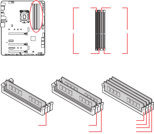
DIMM Slots
DIMMA1 DIMMB1
Channel A Channel B
DIMMA2 DIMMB2
Memory module installation recommendation
⚠
Important
∙
Always insert memory modules in the DIMMA2 slot first.
∙
To ensure system stability for Dual channel mode, memory modules must be of the
same type, number and density.
∙
Some memory modules may operate at a lower frequency than the marked value
when overclocking due to the memory frequency operates dependent on its Serial
Presence Detect (SPD). Go to BIOS and find the DRAM Frequency to set the memory
frequency if you want to operate the memory at the marked or at a higher frequency.
∙
It is recommended to use a more efficient memory cooling system for full DIMMs
installation or overclocking.
∙
The stability and compatibility of installed memory module depend on installed CPU
and devices when overclocking.
∙
Please refer www.msi.com for more information on compatible memory.
DIMMB2 DIMMB2
DIMMB1
DIMMA2
DIMMA2
DIMMA2
DIMMA1