
User's Manual
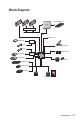
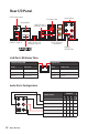
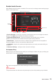
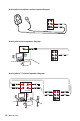
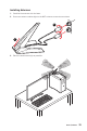
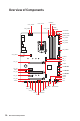
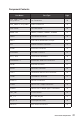
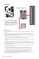
Table Of Contents
- Quick Start
- Specifications
- Package contents
- Block Diagram
- Rear I/O Panel
- Overview of Components
- CPU Socket
- DIMM Slots
- PCI_E1~5: PCIe Expansion Slots
- M2_1~2: M.2 Slots (Key M)
- SATA1~6: SATA 6Gb/s Connectors
- JFP1, JFP2: Front Panel Connectors
- JAUD1: Front Audio Connector
- CPU_PWR1~2, ATX_PWR1: Power Connectors
- JUSBC1: USB 3.2 Gen 2 10Gbps Type-C Connector
- JUSB3: USB 3.2 Gen 1 5Gbps Connector
- JUSB1~2: USB 2.0 Connectors
- JTPM1: TPM Module Connector
- CPU_FAN1, PUMP_FAN1, SYS_FAN1~6: Fan Connectors
- JCI1: Chassis Intrusion Connector
- JCOM1: Serial Port Connector
- JBAT1: Clear CMOS (Reset BIOS) Jumper
- JTBT1: Thunderbolt Add-on Card Connector
- JRTD3: Intel RTD3 Connector
- JRGB1: RGB LED connector
- JRAINBOW1~2: Addressable RGB LED connectors
- JCORSAIR1: CORSAIR Connector
- EZ Debug LED
- LED_SW1: EZ LED Control
- Installing OS, Drivers & Utilities
- UEFI BIOS
- RAID Configuration
- Intel® Optane™ Memory Configuration
- Troubleshooting
- CPU_FAN1, PUMP_FAN1, SYS_FAN1~6: Fan Connectors
- CPU_PWR1~2, ATX_PWR1: Power Connectors
- CPU Socket
- DIMM Slots
- JAUD1: Front Audio Connector
- JBAT1: Clear CMOS (Reset BIOS) Jumper
- JCI1: Chassis Intrusion Connector
- JCOM1: Serial Port Connector
- JCORSAIR1: CORSAIR Connector
- JFP1, JFP2: Front Panel Connectors
- JRAINBOW1~2: Addressable RGB LED connectors
- JRGB1: RGB LED connector
- JRTD3: Intel RTD3 Connector
- JTBT1: Thunderbolt Add-on Card Connector
- JTPM1: TPM Module Connector
- JUSB1~2: USB 2.0 Connectors
- JUSB3: USB 3.2 Gen1 Connector
- JUSBC1: USB 3.2 Gen 2 Type-C Connector
- LED_SW1: EZ LED Control
- M2_1~2: M.2 Slots (Key M)
- PCI_E1~5: PCIe Expansion Slots
- SATA1~6: SATA 6Gb/s Connectors
28
Overview of Components
⚠
Important
∙
Always unplug the power cord from the power outlet before installing or removing
the CPU.
∙
Please retain the CPU protective cap after installing the processor. MSI will deal
with Return Merchandise Authorization (RMA) requests if only the motherboard comes
with the protective cap on the CPU socket.
∙
When installing a CPU, always remember to install a CPU heatsink. A CPU heatsink
is necessary to prevent overheating and maintain system stability.
∙
Confirm that the CPU heatsink has formed a tight seal with the CPU before booting
your system.
∙
Overheating can seriously damage the CPU and motherboard. Always make sure
the cooling fans work properly to protect the CPU from overheating. Be sure to apply
an even layer of thermal paste (or thermal tape) between the CPU and the heatsink to
enhance heat dissipation.
∙
Whenever the CPU is not installed, always protect the CPU socket pins by covering
the socket with the plastic cap.
∙
If you purchased a separate CPU and heatsink/ cooler, Please refer to the
documentation in the heatsink/ cooler package for more details about installation.
∙
This motherboard is designed to support overclocking. Before attempting to
overclock, please make sure that all other system components can tolerate
overclocking. Any attempt to operate beyond product specifications is not
recommended. MSI® does not guarantee the damages or risks caused by inadequate
operation beyond product specifications.
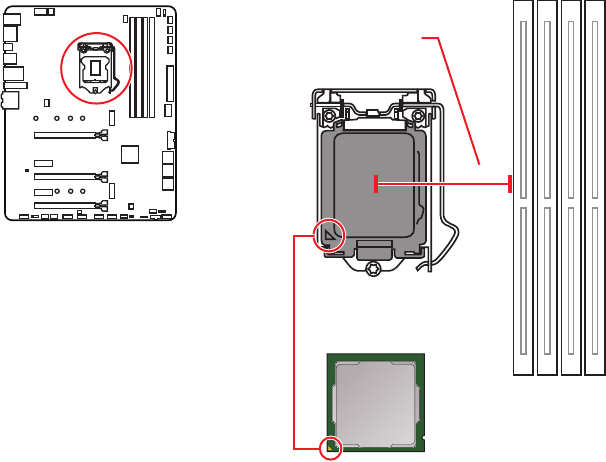
CPU Socket
Introduction to the LGA 1200 CPU
The surface of the LGA 1200 CPU has
two notches and a golden triangle to
assist in correctly lining up the CPU for
motherboard placement. The golden
triangle is the Pin 1 indicator.
49.71 mm
Distance from the center of the
CPU to the nearest DIMM slot.