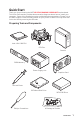
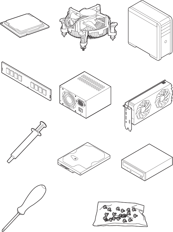
Quick Start Thank you for purchasing the MSI® MPG Z490 GAMING CARBON WIFI motherboard. This Quick Start section provides demonstration diagrams about how to install your computer. Some of the installations also provide video demonstrations. Please link to the URL to watch it with the web browser on your phone or tablet. You may have even link to the URL by scanning the QR code.
Safety Information ∙∙ The components included in this package are prone to damage from electrostatic discharge (ESD). Please adhere to the following instructions to ensure successful computer assembly. ∙∙ Ensure that all components are securely connected. Loose connections may cause the computer to not recognize a component or fail to start. ∙∙ Hold the motherboard by the edges to avoid touching sensitive components.
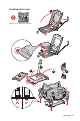
Installing a Processor 2 1 https://youtu.
Installing DDR4 memory http://youtu.
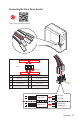
Connecting the Front Panel Header http://youtu.
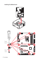
Installing the Motherboard 1 Torque: 3 kgf·cm* 2 BAT1 *3 kgf·cm = 0.3 N·m = 2.
Connecting the Power Connectors http://youtu.
Installing SATA Drives http://youtu.
Installing a Graphics Card http://youtu.
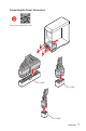
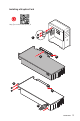
Connecting Peripheral Devices 10 Quick Start
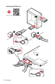
Power On 1 2 3 4 Quick Start 11
Contents Quick Start ............................................................................................................. 1 Preparing Tools and Components .......................................................................... 1 Safety Information .................................................................................................. 2 Installing a Processor ............................................................................................. 3 Installing DDR4 memory .........
JCOM1: Serial Port Connector ............................................................................. 39 JBAT1: Clear CMOS (Reset BIOS) Jumper ........................................................... 40 JTBT1: Thunderbolt Add-on Card Connector ...................................................... 40 JRTD3: Intel RTD3 Connector .............................................................................. 40 JRGB1: RGB LED connector ...................................................................
Specifications CPU Chipset Supports 10th Gen Intel® Core™ and Pentium® Gold / Celeron® processors for LGA 1200 socket* * Please go to www.intel.com for more compatibility information. * Onboard graphics output are disabled when using F SKU processors.
Continued from previous page Intel® Z490 Chipset ∙∙ 6x SATA 6Gb/s ports*/** ∙∙ 2x M.2 slots (Key M) ▪▪M2_1 supports up to PCIe 3.0 x4 and SATA 6Gb/s, 2242/ 2260/ 2280/ 22110 storage devices* Storage ▪▪M2_2 supports up to PCIe 3.0 x4 and SATA 6Gb/s, 2242/ 2260/ 2280 storage devices** ▪▪Intel® Optane™ Memory Ready*** ▪▪Supports Intel® Smart Response Technology for Intel Core™ processors * SATA2 will be unavailable when installing M.2 SATA SSD in the M2_1 slot.
Continued from previous page Intel® AX201 Wireless LAN & Bluetooth® ∙∙ The Wireless module is pre-installed in the M.2 (Key-E) slot ∙∙ Supports MU-MIMO TX/RX, 2.4GHz/ 5GHz (160MHz) up to 2.4Gbps ∙∙ Supports 802.11 a/b/g/n/ac/ax ∙∙ WiFi 6 pre-certified ∙∙ Supports Bluetooth® 5.1, FIPS, FISMA ∙∙ 1x 24-pin ATX main power connector ∙∙ 1x 8-pin ATX 12V power connector ∙∙ 1x 4-pin ATX 12V power connector ∙∙ 6x SATA 6Gb/s connectors ∙∙ 2x M.2 slots (M-Key) ∙∙ 1x USB 3.2 Gen 2 10Gbps Type-C port ∙∙ 1x USB 3.
Continued from previous page LED Features ∙∙ 1x EZ LED Control switch ∙∙ 4x EZ Debug LED ∙∙ 1 x PS/2 keyboard/ mouse combo port ∙∙ 2 x USB 2.0 Type-A ports ∙∙ 1x Display port Back Panel Connectors ∙∙ 1x HDMI port ∙∙ 1 x USB 3.2 Gen 2x2 20Gbps Type-C port ∙∙ 4 x USB 3.
Continued from previous page ∙∙ Gaming Mode ∙∙ Gaming Hotkey ∙∙ LAN Manager ∙∙ Mystic Light ∙∙ Ambient Link Dragon Center Features ∙∙ User Scenario ∙∙ Hardware Monitor ∙∙ True Color ∙∙ Live Update ∙∙ DPC Latency Tuner Please refer to http://download.msi. com/manual/mb/DRAGONCENTER2. pdf for more details. ∙∙ Speed Up ∙∙ Smart Tool ∙∙ Super Charger ∙∙ Audio ▪▪Audio Boost 4 ∙∙ Network ▪▪2.5G LAN ▪▪LAN Manager with Realtek 8125B ▪▪Intel WiFi ∙∙ Cooling Special Features ▪▪M.
Continued from previous page ∙∙ Performance ▪▪Multi GPU – SLI Technology ▪▪Multi GPU – CrossFire Technology ▪▪DDR4 Boost ▪▪Core Boost ▪▪Game Boost ▪▪Lightning USB 20G Special Features ▪▪USB 3.
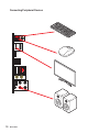
Package contents Please check the contents of your motherboard package. It should contain: Motherboard Cable MPG Z490 GAMING CARBON WIFI SATA 6G cables (2 cables/pack) 1 LED JCORSAIR cable 1 LED JRGB Y cable LED JRAINBOW cable Wi-Fi Antenna Accessories Application Documentation ⚠⚠Important M.2 screws (3 pcs.
Block Diagram 2 Channel DDR4 Memory Processor Switch PCI Express Bus DMI 3.0 2x PCIe x1 slot 1x SATA 6Gb/s Switch 1x M.2 1x Intel AX201 Wireless LAN 1x M.2 1x Realtek 2.5G LAN 2x SATA 6Gb/s PCH Switch JHL7540 3x SATA 6Gb/s ASMEDIA 3241 5x USB 3.2 Gen2 1x USB 3.2 Gen2 x 2 2x USB 3.2 Gen1 6x USB 2.
Rear I/O Panel PS/2 Combo port DisplayPort USB 3.2 Gen 2 (10Gbps) Type-A Wi-Fi Antenna connectors USB 3.2 Gen 2x2 (20Gbps) Type-C USB 2.0 Type-A LAN Port LED Status Table Link/ Activity LED Speed LED Off Off Status Description Yellow (2.5Gb LAN) Linked Blinking Audio Ports 2.5 Gbps LAN No link Data activity Optical S/PDIF-Out Status 2.5 Gbps LAN Green 100 Mbps/ 1 Gbps Orange 10 Mbps 2.
Realtek Audio Console After Realtek Audio Console is installed. You can use it to change sound settings to get better sound experience. Application Enhancement Device Selection Main Volume Connector Settings Jack Status ∙∙ Device Selection - allows you to select a audio output source to change the related options. The check sign indicates the devices as default.
Audio jacks to headphone and microphone diagram Audio jacks to stereo speakers diagram AUDIO INPUT Audio jacks to 7.
Installing Antennas 1. Combine the antenna with the base. 2. Screw two antenna cables tight to the WiFi antenna connectors as shown. 2 1 3. Place the antenna as high as possible.
Overview of Components DIMMA1 CPU Socket CPU_PWR2 CPU_FAN1 CPU_PWR1 DIMMA2 DIMMB1 DIMMB2 JCORSAIR1 JRAINBOW2 PUMP_FAN1 SYS_FAN2 SYS_FAN1 SYS_FAN6 ATX_PWR1 SYS_FAN3 JUSBC1 M2_1 M2_2 PCI_E1 JUSB3 BAT1 SATA▼1▲2 PCI_E2 JBAT1 PCI_E3 SATA▼3▲4 SATA▼5▲6 JSMB1 PCI_E4 JRTD3 PCI_E5 JAUD1 JCI1 SYS_FAN5 JTPM1 JCOM1 Overview of Components JUSB2 JPWRLED1 JUSB1 26 JTBT1 LED_SW1 JRAINBOW1 JRGB1 SYS_FAN4 JFP2 JFP1
Component Contents Port Name Port Type Page CPU_FAN1, PUMP_FAN1, SYS_FAN1~6 Fan Connectors 38 CPU Socket LGA 1200 socket 28 CPU_PWR1~2, ATX_PWR1 DIMM Slots JAUD1 JBAT1 JCI1 JCOM1 JCORSAIR1 JFP1, JFP2 JRAINBOW1~2 JRGB1 JRTD3 JTBT1 JTPM1 JUSB1~2 JUSB3 JUSBC1 LED_SW1 M2_1~2 PCI_E1~5 SATA1~6 Power Connectors 35 DIMMA1, DIMMA2, DIMMB1, DIMMB2 Front Audio Connector Clear CMOS (Reset BIOS) Jumper 39 Serial Port Connector 39 CORSAIR Connector 43 Front Panel Connectors Addressable RGB LED
CPU Socket Distance from the center of the CPU to the nearest DIMM slot. 49.71 mm Introduction to the LGA 1200 CPU The surface of the LGA 1200 CPU has two notches and a golden triangle to assist in correctly lining up the CPU for motherboard placement. The golden triangle is the Pin 1 indicator. ⚠⚠Important ∙∙ Always unplug the power cord from the power outlet before installing or removing the CPU. ∙∙ Please retain the CPU protective cap after installing the processor.
DIMM Slots DIMMA1 Channel A DIMMA2 DIMMB1 Channel B DIMMB2 Memory module installation recommendation DIMMA2 ⚠⚠Important DIMMA2 DIMMB2 DIMMA1 DIMMA2 DIMMB1 DIMMB2 ∙∙ Always insert memory modules in the DIMMA2 slot first. ∙∙ To ensure system stability for Dual channel mode, memory modules must be of the same type, number and density.
PCI_E1~5: PCIe Expansion Slots PCI_E1: PCIe 3.0 x16 (CPU) BAT1 PCI_E2: PCIe 3.0 x1 (PCH) PCI_E3: PCIe 3.0 x8 (CPU) PCI_E4: PCIe 3.0 x1 (PCH) PCI_E5: PCIe 3.0 x4 (PCH) Multiple graphics cards installation recommendation Slot Single 2-Way 3-Way* PCI_E1 (CPU) @ 3.0 x16 @ 3.0 x8 @ 3.0 x8 PCI_E3 (CPU) — @ 3.0 x8 @ 3.0 x8 3.0 x4 3.0 x4 @ 3.0 x4 PCI_E2 (PCH) PCI_E4 (PCH) PCI_E5 (PCH) 3.0 x1 3.0 x1 3.0 x1 3.0 x1 (─: unavailable, @: graphics card,*: CrossFire only) ⚠⚠Important 3.0 x1 3.
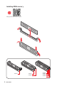
M2_1~2: M.2 Slots (Key M) ⚽⚽Video Demonstration Watch the video to learn how to Install M.2 module. http://youtu.be/JCTFABytrYA M2_1 ⚠⚠Important M2_2 ∙∙ Intel® RST only supports PCIe M.2 SSD with UEFI ROM. ∙∙ Intel® Optane™ Memory Ready for all M.2 slots. Installing M.2 module 1. Loosen the screws of M.2 SHIELD FROZR heatsink. 2. Remove the M.2 SHIELD FROZR and remove the protective films from the thermal pads.
3. Move and fasten the M.2 standoff to the appropriate position for your M.2 SSD, or remove the M.2 standoff if your M.2 SSD length is same as the length of M.2 heatsink to avoid damage to the M.2 SSD. 4. Insert your M.2 SSD into the M.2 slot at a 30-degree angle. 5. Secure the M.2 SSD in place with the M.2 screw, or skip this step if you remove the M.2 standoff in step 3. 4 M.2 screw 5 M.2 standoff 30º 3 heatsink standoff 6. Put the M.2 SHIELD FROZR heatsink back in place and secure it.
SATA1~6: SATA 6Gb/s Connectors These connectors are SATA 6Gb/s interface ports. Each connector can connect to one SATA device. SATA6 SATA5 SATA4 SATA3 SATA2 SATA1 ⚠⚠Important ∙∙ Please do not fold the SATA cable at a 90-degree angle. Data loss may result during transmission otherwise. ∙∙ SATA cables have identical plugs on either sides of the cable. However, it is recommended that the flat connector be connected to the motherboard for space saving purposes.
JFP1, JFP2: Front Panel Connectors These connectors connect to the switches and LEDs on the front panel.
CPU_PWR1~2, ATX_PWR1: Power Connectors These connectors allow you to connect an ATX power supply. 1 2 3 4 1 24 1 13 Ground +12V +12V 7 Ground Ground 5 6 +12V 8 4 2 3 1 +12V CPU_PWR2 3 +3.3V 13 +3.3V 3 Ground 15 Ground 5 Ground 17 7 Ground 19 6 +3.3V +5V +5V 4 +12V 1 14 18 Ground 20 10 +12V 22 12 5VSB +12V +3.
JUSBC1: USB 3.2 Gen 2 10Gbps Type-C Connector This connector allows you to connect USB 3.2 Gen 2 10Gbps Type-C connector on the front panel. The connector possesses a foolproof design. When you connect the cable, be sure to connect it with the corresponding orientation. USB Type-C Cable JUSBC1 USB Type-C port on the front panel JUSB3: USB 3.2 Gen 1 5Gbps Connector This connector allows you to connect USB 3.2 Gen 1 5Gbps ports on the front panel.
JUSB1~2: USB 2.0 Connectors These connectors allow you to connect USB 2.0 ports on the front panel. 1 VCC 3 10 1 9 USB0- 5 USB1+ 8 No Pin VCC USB1- 6 Ground 9 2 4 USB0+ 7 ⚠⚠Important 2 Ground 10 NC ∙∙ Note that the VCC and Ground pins must be connected correctly to avoid possible damage. ∙∙ In order to recharge your iPad,iPhone and iPod through USB ports, please install MSI® DRAGON CENTER utility. JTPM1: TPM Module Connector This connector is for TPM (Trusted Platform Module).
CPU_FAN1, PUMP_FAN1, SYS_FAN1~6: Fan Connectors Fan connectors can be classified as PWM (Pulse Width Modulation) Mode or DC Mode. PWM Mode fan connectors provide constant 12V output and adjust fan speed with speed control signal. DC Mode fan connectors control fan speed by changing voltage. CPU_FAN1 can automatically detect PWM and DC mode of CPU fan. However, you can follow the instruction below to adjust the fan connector to PWM or DC Mode manually.
JCI1: Chassis Intrusion Connector This connector allows you to connect the chassis intrusion switch cable. Normal (default) Trigger the chassis intrusion event Using chassis intrusion detector 1. Connect the JCI1 connector to the chassis intrusion switch/ sensor on the chassis. 2. Close the chassis cover. 3. Go to BIOS > SETTINGS > Security > Chassis Intrusion Configuration. 4. Set Chassis Intrusion to Enabled. 5. Press F10 to save and exit and then press the Enter key to select Yes. 6.
JBAT1: Clear CMOS (Reset BIOS) Jumper There is CMOS memory onboard that is external powered from a battery located on the motherboard to save system configuration data. If you want to clear the system configuration, set the jumpers to clear the CMOS memory. Keep Data (default) Clear CMOS/ Reset BIOS Resetting BIOS to default values 1. Power off the computer and unplug the power cord. 2. Use a jumper cap to short JBAT1 for about 5-10 seconds. 3. Remove the jumper cap from JBAT1. 4.
JRGB1: RGB LED connector The JRGB connector allows you to connect the 5050 RGB LED strips 12V. 1 3 1 +12V R 2 4 G B RGB LED Strip Connection 1 G R B RGB extension cable JRGB connector 5050 RGB LED strips 12V RGB LED Fan Connection JRGB connector 1 G R B 1 System Fan connector RGB LED Fan ⚠⚠Important ∙∙ The JRGB connector supports up to 2 meters continuous 5050 RGB LED strips (12V/G/R/B) with the maximum power rating of 3A (12V).
JRAINBOW1~2: Addressable RGB LED connectors The JRAINBOW connectors allow you to connect the WS2812B Individually Addressable RGB LED strips 5V.
JCORSAIR1: CORSAIR Connector The JCORSAIR1 connector allows you to connect the CORSAIR Individually Addressable Lighting PRO RGB LED strips 5V or CORSAIR RGB fans with the CORSAIR fan hub. Once all items are connected properly, you can control the CORSAIR RGB LED strips and fans with MSI's software.
EZ Debug LED These LEDs indicate the debug status of the motherboard. CPU - indicates CPU is not detected or fail. DRAM - indicates DRAM is not detected or fail. VGA - indicates GPU is not detected or fail. BOOT - indicates the booting device is not detected or fail. LED_SW1: EZ LED Control This switch is used to switch on/ off all the LEDs of motherboard.
Installing OS, Drivers & Utilities Please download and update the latest utilities and drivers at www.msi.com Installing Windows® 10 1. Power on the computer. 2. Insert the Windows® 10 installation disc/USB into your computer. 3. Press the Restart button on the computer case. 4. Press F11 key during the computer POST (Power-On Self Test) to get into Boot Menu. 5. Select the Windows® 10 installation disc/USB from the Boot Menu. 6. Press any key when screen shows Press any key to boot from CD or DVD...
UEFI BIOS MSI UEFI BIOS is compatible with UEFI (Unified Extensible Firmware Interface) architecture. UEFI has many new functions and advantages that traditional BIOS cannot achieve, and it will completely replace BIOS in the future. The MSI UEFI BIOS uses UEFI as the default boot mode to take full advantage of the new chipset’s capabilities. However, it still has a CSM (Compatibility Support Module) mode to be compatible with older devices.
BIOS Setup The default settings offer the optimal performance for system stability in normal conditions. You should always keep the default settings to avoid possible system damage or failure booting unless you are familiar with BIOS. ⚠⚠Important ∙∙ BIOS items are continuously update for better system performance. Therefore, the description may be slightly different from the latest BIOS and should be for reference only. You could also refer to the HELP information panel for BIOS item description.
Resetting BIOS You might need to restore the default BIOS setting to solve certain problems. There are several ways to reset BIOS: ∙∙ Go to BIOS and press F6 to load optimized defaults. ∙∙ Short the Clear CMOS jumper on the motherboard. ⚠⚠Important Be sure the computer is off before clearing CMOS data. Please refer to the Clear CMOS jumper section for resetting BIOS.
Updating the BIOS with MSI DRAGON CENTER Before updating: Make sure the LAN driver is already installed and the internet connection is set properly. Updating BIOS: 1. Install and launch MSI DRAGON CENTER and go to Support page. 2. Select Live Update and click on Advance button. 3. Click on Scan button to search the latest BIOS file. 4. Select the BIOS file and click on Download icon to download and install the latest BIOS file. 5. Click Next and choose In Windows mode.
EZ Mode At EZ mode, it provides the basic system information and allows you to configure the basic setting. To configure the advanced BIOS settings, please enter the Advanced Mode by pressing the Setup Mode switch or F7 function key. XMP Profile Setup Mode switch Screenshot Search Language System information GAME BOOST Boot device priority bar Component Information M-Flash Favorites Hardware Monitor Function buttons ∙∙ GAME BOOST - click on it to toggle the GAME BOOST for overclocking.
∙∙ Language - allows you to select language of BIOS setup. ∙∙ System information - shows the CPU/ DDR speed, CPU/ MB temperature, MB/ CPU type, memory size, CPU/ DDR voltage, BIOS version and build date. ∙∙ Boot device priority bar - you can move the device icons to change the boot priority. The boot priority from high to low is left to right. ∙∙ Component Information - click on the CPU, Memory, Storage, Fan Info and Help buttons to show the information of connected component.
▪▪To add a BIOS item to a favorite menu 1. Select a BIOS item not only on BIOS menu but also on search page. 3. Choose a favorite page and click on OK. 2. Right-click or press F2 key. ▪▪To delete a BIOS item from favorite menu 1. Select a BIOS item on favorite menu. 3. Choose Delete and click on OK. 2. 52 Right-click or press F2 key.
Advanced Mode Press Setup Mode switch or F7 function key can switch between EZ Mode and Advanced Mode in BIOS setup. BIOS menu selection BIOS menu selection Menu display ∙∙ BIOS menu selection - the following options are available: ▪▪SETTINGS - allows you to specify the parameters for chipset and boot devices. ▪▪OC - allows you to adjust the frequency and voltage. Increasing the frequency may get better performance. ▪▪M-FLASH - provides the way to update BIOS with a USB flash drive.
SETTINGS Menu This menu allows you to specify the parameters for system, chipset and boot devices. ▶▶System Status sub-menu The System Status sub-menu allows you to set the system clock and view system information. ▶▶System Date Sets the system date. Use tab key to switch between date elements. The format is . Day of the week, from Sun to Sat, determined by BIOS. Read-only. The month from Jan. through Dec.
▶▶Intel (R) Thunderbolt sub-menu Sets the Intel thunderbolt device function. This sub-menu is only available when using the Intel thunderbolt device. ▶▶USB Configuration sub-menu Sets the onboard USB controller and device function. Press Enter to enter the sub-menu. ▶▶Super IO Configuration sub-menu Sets system Super I/O chip parameters including LPT and COM ports. Press Enter to enter the sub-menu. ▶▶Power Management Setup sub-menu Sets system Power Management of ErP and AC Power Loss behaviors.
OC Menu This menu allows you to configure the frequencies and voltages for overclocking. Please note that, higher frequency and voltage may benefit overclocking capability but cause system un-stability. ⚠⚠Important ∙∙ Overclocking your PC manually is only recommended for advanced users. ∙∙ Overclocking is not guaranteed, and if done improperly, it could void your warranty or severely damage your hardware.
▶▶Core X X of X xxxx MHz [Auto] Allows you to set the CPU ratios for different number of active cores. These items only appear when CPU Ratio Apply Mode set to Per Core. ▶▶Turbo Ratio Offset Value [Auto] Sets the CPU Turbo ratio offset value. This item only appears when CPU Ratio Apply Mode set to Turbo Ratio Offset. ▶▶CPU Ratio Mode [Dynamic Mode]* Selects the CPU Ratio operating mode. This item will appear when you set the CPU ratio manually. [Fixed Mode] [Dynamic Mode] Fixes the CPU ratio.
▶▶Clockgen Features sub-menu Press Enter to enter the sub-menu. Sets the detailed clockgen features. ▶▶Extreme Memory Profile (XMP) [Disabled] XMP (Extreme Memory Profile) is the overclocking technology by memory module. Please enable XMP or select a profile of memory module for overclocking the memory. This item will be available when the memory modules that support XMP is installed. ▶▶Memory Try It ! [Disabled] It can improve memory compatibility or performance by choosing optimized memory preset.
▶▶DRAM Voltages control [Auto] These options allow you to set the voltages related to memory. If set to Auto, BIOS will set these voltages automatically or you can set it manually. ▶▶PCH Voltages control [Auto] These options allow you to set the voltages related to PCH. If set to Auto, BIOS will set these voltages automatically or you can set it manually. ▶▶CPU Memory Changed Detect [Enabled]* Enables or disables the system to issue a warning message during boot when the CPU or memory has been replaced.
M-FLASH Menu M-FLASH provides the way to update BIOS with a USB flash drive. Please download the latest BIOS file that matches your motherboard model from MSI website, save the BIOS file into your USB flash drive. And then follow the steps below to update BIOS. 1. Insert the USB flash drive that contains the update file into the computer. 2. Click on M-FLASH tab, a demand message will be prompted. Click on Yes to reboot and enter the flash mode. 3.
OC PROFILE Menu This menu allows you to set the BIOS profiles. ▶▶Overclocking Profile 1/ 2/ 3/ 4/ 5/ 6 Overclocking Profile 1/ 2/ 3/ 4/ 5/ 6 management. Press Enter to enter the sub-menu. ▶▶Set Name for Overclocking Profile 1/ 2/ 3/ 4/ 5/ 6 Name the current overclocking profile. ▶▶Save Overclocking Profile 1/ 2/ 3/ 4/ 5/ 6 Save the current overclocking profile. ▶▶Load Overclocking Profile 1/ 2/ 3/ 4/ 5/ 6 Load the current overclocking profile.
HARDWARE MONITOR Menu This menu allows you to adjust the fan speed manually and monitor CPU/ system voltage. Select a temperature curve line (white) to be showed in Fan operating window Select a fan mode for target fan Select a fan to be configured Click to enable the Smart Fan Smart Fan duty information Fan operating window Setting Buttons Temperature information Voltage information ∙∙ Smart Fan - This setting enables/disables the Smart Fan function.
Adjusting fans 1. Selects a fan that you want to adjust and to display the fan duty curve line (yellow) in fan operating windows. 2. Click and drag the duty points to adjust the fan speed. Select a fan to be adjusted Duty points ⚠⚠Important The pictures in this section are for reference only and may vary from the motherboard you purchased.
RAID Configuration Below are the different types of a RAID. RAID 0 RAID 1 RAID 5 breaks the data into blocks which are written to separate hard drives. Spreading the hard drive I/O load across independent channels greatly improves I/O performance. provides data redundancy by mirroring data between the hard drives and provides enhanced read performance. provides data striping at the byte level and also stripe error correction information. This results in excellent performance and good fault tolerance.
5. Press F10 to save configuration and exit, and then reboot and press Delete key to enter BIOS Setup menu. 6. Go to BIOS > SETTING > Advanced > Intel(R) Rapid Storage Technology submenu. Creating RAID Volume 1. As previously mentioned, enable Intel(R) Rapid Storage Technology. 2. Enter Create RAID Volume screen. The following screen appears: 3. Specify a Name for RAID volume. 4. Select the RAID Level best suited to your usage model in RAID Level. 5.
Removing a RAID Volume Here you can delete the RAID volume, but please be noted that all data on RAID drives will be lost. ⚠⚠Important If your system currently boots to RAID and you delete the RAID volume, your system will become unbootable. 1. Go to BIOS > SETTING > Advanced > Intel(R) Rapid Storage Technology. 2. Select the RAID volume from the Intel(R) Rapid Storage Technology screen to enter the RAID VOLUME INFO screen. 3.
Resetting Disks to Non-RAID 1. Go to BIOS > SETTING > Advanced > Intel(R) Rapid Storage Technology. 2. Select the RAID volume from the Intel(R) Rapid Storage Technology screen to enter the RAID VOLUME INFO screen. 3. Select the disk and press Enter to enter PHYSICAL DISK INFO screen. 4. Select Reset to non-RAID item and press Enter to delete the RAID volume and remove any RAID structures from the drives. The following screen appears: 5.
Rebuilding RAID Array A RAID 1, RAID 5 or RAID 10 volume is reported as Degraded when one of its hard drive members fails or is temporarily disconnected, and data mirroring is lost. As a result, the system can only utilize the remaining functional hard drive member. To reestablish data mirroring and restore data redundancy, refer to the procedure below that corresponds to the current situation. 1. Power off. 2. Replace the failed hard drive with a new one that is of equal or greater capacity. 3.
Installing RAID Driver New Operating System Installation The following details the installation of the drivers while installing Windows 10 x64 bit Editions or newer operating system. 1. During the operating system installation, after selecting the location to install Windows click on Load driver button to install a third party RAID driver. 2. When prompted, insert the USB flash drive with Intel RAID Drivers and then click Browse. ▪▪To make an Intel RAID Drivers USB flash drive.
Intel® Optane™ Memory Configuration Intel® Optane™ memory can accelerate the Windows 10 64bit operating system. This section describes how to install and remove the Intel® Optane™ memory. System Requirements ∙∙ Intel® Optane™ memory ready MSI® motherboards ∙∙ Supported 8th Gen, or later, Intel® Core™ - i Processor ∙∙ System BIOS that supports the Intel® Rapid Storage Technology (Intel® RST) 16 or later driver ∙∙ Operating system: Windows 10 64 bit (UEFI mode).
5. Enable Intel® Optane™ Memory. ▫▫Run the Intel® Rapid Storage Technology software. ▫▫Click Intel® Optane™ Memory tab and click Enable. ▫▫Click Yes in the dialog. 6. Reboot System. ⚠⚠WARNING Once you enable Intel® Optane™ memory, in order to prevent seriously damage your operating system, please follow the cautions listed below. ∙∙ DO NOT set the SATA mode back to AHCI in BIOS. ∙∙ DO NOT revert back to older version of the BIOS. ∙∙ DO NOT remove the Intel® Optane™ memory module.
Removing the Intel® Optane™ memory If you no longer want to use Intel® Optane™ memory, you have to disable the Intel® Optane™ memory before removing the Intel® Optane™ memory module to avoid operating system damage. Please follow the steps below to remove the Intel® Optane™ memory. 1. Disable Intel® Optane™ Memory. ▫▫Disable Intel® Optane™ Memory via the Intel® Optane™ memory application (Intel® Rapid Storage Technology). ▫▫Click Yes in the dialog. ▫▫Reboot System. 2. Disable M.
Troubleshooting Before sending the motherboard for RMA repair, try to go over troubleshooting guide first to see if your got similar symptoms as mentioned below. The power is not on. ∙∙ Connect the AC power cord to an electrical outlet securely. ∙∙ Check if all ATX power connectors like ATX_PWR1, CPU_PWR1 are connected from the power supply to the motherboard? ∙∙ Some power supply units have a power button on the rear side, make sure the button is turned on.
Regulatory Notices FCC Compliance Statement Note: This equipment has been tested and found to comply with the limits for a Class B digital device, pursuant to part 15 of the FCC Rules. These limits are designed to provide reasonable protection against harmful interference in a residential installation. This equipment generates, uses and can radiate radio frequency energy and, if not installed and used in accordance with the instructions, may cause harmful interference to radio communications.
covered electronic equipment will be obligated to take back such products at the end of their useful life. MSI will comply with the product take back requirements at the end of life of MSI-branded products that are sold into the EU. You can return these products to local collection points. términos de recogida de sus productos vendidos en la Unión Europea al final de su periodo de vida.
ČESKY Záleží nám na ochraně životního prostředí - společnost MSI upozorňuje... Podle směrnice Evropské unie (“EU”) o likvidaci elektrických a elektronických výrobků 2002/96/ EC platné od 13. srpna 2005 je zakázáno likvidovat “elektrické a elektronické výrobky” v běžném komunálním odpadu a výrobci elektronických výrobků, na které se tato směrnice vztahuje, budou povinni odebírat takové výrobky zpět po skončení jejich životnosti.
MS-7C73主板产品中有害物质的名称及含量 部件名称 铅 汞 镉 有害物质 六价铬 多溴联苯 多溴二苯醚 ○ ○ ○ (Pb) (Hg) (Cd) (Cr(VI)) 电池** ╳ ○ ○ ○ ○ ○ 外部信号连接头 ╳ ○ ○ ○ ○ ○ 印刷电路板组件* 线材 本表格依据 SJ/T 11364 的规定编制。 ╳ ╳ ○ ○ ○ ○ (PBB) ○ ○ (PBDE) ○ ○: 表示该有害物质在该部件所有均质材料中的含量均在 GB/T 26572 规定的限量要求以下。 ╳: 表示该有害物质至少在该部件的某一均质材料中的含量超出 GB/T 26572 规定的限量要求,但所有部件都符合 欧盟RoHS要求。 * 印刷电路板组件: 包括印刷电路板及其构成的零部件。 ** 电池本体上如有环保使用期限标识,以本体标识为主。 ■ 上述有毒有害物质或元素清单会依型号之部件差异而有所增减。 ■ 產品部件本体上如有环保使用期限标识,以本体标识为主。 限用物質含有情況標示聲明書 設備名稱:電腦主機板 單元 電路板 電子元件 金屬機構件