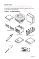
Quick Start Thank you for purchasing the MSI® MPG X570 GAMING EDGE WIFI motherboard. This Quick Start section provides demonstration diagrams about how to install your computer. Some of the installations also provide video demonstrations. Please link to the URL to watch it with the web browser on your phone or tablet. You may have even link to the URL by scanning the QR code.
Safety Information y The components included in this package are prone to damage from electrostatic discharge (ESD). Please adhere to the following instructions to ensure successful computer assembly. y Ensure that all components are securely connected. Loose connections may cause the computer to not recognize a component or fail to start. y Hold the motherboard by the edges to avoid touching sensitive components.
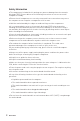
Installing a Processor https://youtu.
Important If you are installing the screw-type CPU heatsink, please follow the figure below to remove the retention module first and then install the heatsink.
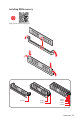
Installing DDR4 memory http://youtu.
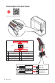
Connecting the Front Panel Header http://youtu.
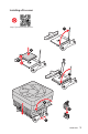
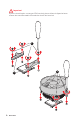
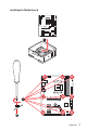
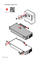
Installing the Motherboard 1 BAT1 2 Quick Start 7
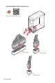
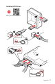
Connecting the Power Connectors http://youtu.
Installing SATA Drives http://youtu.
Installing a Graphics Card http://youtu.
Connecting Peripheral Devices Proc esso r wit h int egra ted g raph i cs Quick Start 11
Power On 1 2 3 4 12 Quick Start
Contents Quick Start ............................................................................................................. 1 Preparing Tools and Components .......................................................................... 1 Safety Information .................................................................................................. 2 Installing a Processor ............................................................................................. 3 Installing DDR4 memory .........
JRGB1~2: RGB LED connectors ........................................................................... 40 JRAINBOW1~2: Addressable RGB LED connectors ............................................. 41 Installing OS, Drivers & Utilities ......................................................................... 42 Installing Windows® 10 ......................................................................................... 42 Installing Drivers ................................................................
Specifications CPU Supports 2nd and 3rd Gen AMD Ryzen™ / Ryzen™ with Radeon™ Vega Graphics and 2nd Gen AMD Ryzen™ with Radeon™ Graphics Desktop Processors for Socket AM4 Chipset AMD® X570 Chipset y 4x DDR4 memory slots, support up to 128GB* (depending on the processor) Supports DDR4 1866/ 2133/ 2400/ 2666 MHz by JEDEC, and 2666/ 2800/ 2933/ 3000/ 3066/ 3200/ 3466/ 3600/ 3733/ 3866/ 4000/ 4133/ 4266/ 4400 MHz by A-XMP OC MODE Memory y Dual channel memory architecture y Supports non-ECC UDIMM memory y
Continued from previous page Intel® Dual Band Wireless-AC 3168 Wireless LAN & Bluetooth® Supports 802.11 a/b/g/n/ac/ax, dual band (2.4GHz, 5GHz) up to 433 Mbps Supports Dual Mode Bluetooth® 2.1, 2.1+EDR, 3.0, 4.0, BLE, 4.2 The Wireless module is pre-install in the M2_3 (Key-E) slot y 6x SATA 6Gb/s ports y 2x M.2 slots (Key M)* M2_1 slot (from AMD® Processor) Supports PCIe 4.0 x4 (3rd Gen AMD Ryzen™) Storage Supports PCIe 3.
Continued from previous page y AMD® X570 Chipset 2x USB 3.2 Gen 2 (SuperSpeed USB 10Gbps) Type-A ports on the back panel 4x USB 3.2 Gen 1 (SuperSpeed USB) ports through the internal USB 3.2 Gen1 connector USB 6x USB 2.0 (High-speed USB) ports (2 Type-A ports on the back panel, 4 ports available through the internal USB 2.0 connectors) y AMD® Processor 2x USB 3.2 Gen2 (3rd Gen AMD Ryzen™) or USB 3.
Continued from previous page y 1x Flash BIOS Button y 1x PS/2 keyboard/ mouse combo port y 2x USB 2.0 ports y 2x WiFi/ Bluetooth antenna jacks y 2x USB 3.2 Gen 1 ports Back Panel Connectors y 1x HDMI port y 1x USB 3.2 Gen 2/ 1 Type A port y 1x USB 3.2 Gen 2/1 Type C port y 2x USB 3.
Continued from previous page y DRAGON OPTIMIZATION y OC Performance Dragon Center Features y Hardware Monitor y True Color y Mystic Light y Live Update Please refer to http://download.msi. com/manual/mb/DRAGONCENTER2. pdf for more details. y Audio Nahimic 3 Audio Boost 4 y Network Intel WiFi y Storage Lightning Gen 4 M.2 Turbo M.
Continued from previous page y Performance Multi GPU-CrossFire Technology DDR4 Boost Core Boost GAME Boost Special Features USB with type A+C AMD Turbo USB 3.2 Gen 2 y BIOS Click BIOS 5 Flash BIOS y Certification GAMING Certified Package contents Please check the contents of your motherboard package. It should contain: Motherboard Cable Accessories Application DVD Documentation MPG X570 GAMING EDGE WIFI SATA 6Gb/s Cables 2 RAINBOW RGB LED Extension Cable 80cm 1 Antenna Set 1 8.
Block Diagram 2 Channel DDR4 Memory Processor 1x M.2 PCI Express Bus 2x USB 3.2 Gen1 2x USB 3.2 Gen2 1x M.2 PCIE Realtek ALC1220 6x SATA 6Gb/s PCH Front Audio Jacks Rear Audio Jacks NUVOTON 6797 6x USB 2.0 4x USB 3.2 Gen1 1x Intel Wi-Fi 3168 2x USB 3.
Rear I/O Panel Wi-Fi Antenna connectors PS/2 USB 3.2 Gen1 Type-A Audio Ports LAN USB 3.2 Gen 2 Type-A* Flash BIOS Button Flash BIOS Port USB 3.2 Gen 2 Type-A USB 2.0 Type-A Optical S/PDIF-Out USB 3.2 Gen 2 Type-C* *USB 3.2 Gen2 (3rd Gen AMD Ryzen™) or USB 3.2 Gen1 (2nd Gen AMD Ryzen™/Ryzen™ with Radeon™ Vega Graphics and 2nd Gen AMD Ryzen™ with Radeon™Graphics) y Flash BIOS Port/ Button - Please refer to page 45 for Updating BIOS with Flash BIOS Button.
Realtek Audio Console After Realtek Audio Console is installed. You can use it to change sound settings to get better sound experience. Application Enhancement Device Selection Main Volume Connector Settings Jack Status y Device Selection - allows you to select a audio output source to change the related options. The check sign indicates the devices as default.
Audio jacks to headphone and microphone diagram Audio jacks to stereo speakers diagram AUDIO INPUT Audio jacks to 7.
Installing antennas 1. Screw the antennas tight to the antenna connectors as shown below. 2. Orient the antennas.
Overview of Components Processor Socket CPU_FAN1 CPU_PWR2 JRGB2 CPU_PWR1 JRAINBOW2 PUMP_FAN1 DIMMB2 DIMMB1 DIMMA2 DIMMA1 ATX_PWR1 M2_1 SATA▼5▲6 JBAT1 SATA▼3▲4 PCI_E2 SATA▼1▲2 BAT1 PCI_E1 M2_2 PCI_E3 JUSB4 PCI_E4 JCI1 JFP2 JRAINBOW1 JFP1 PCI_E5 JAUD1 JRGB1 JTPM1 SYS_FAN1 JUSB2 JUSB1 SYS_FAN2 SYS_FAN3 JCOM1 SYS_FAN4 26 Overview of Components JUSB3
Component Contents Port Name Port Type Page CPU_FAN1, PUMP_FAN1, SYS_FAN1~4 Fan Connectors 35 CPU_PWR1~2, ATX_PWR1 Power Connectors 34 CPU Socket AM4 CPU Socket 28 DIMMA1/A2/B1/B2 DIMM Slots 29 JAUD1 Front Audio Connector 37 JBAT1 Clear CMOS (Reset BIOS) Jumper 39 JCI1 Chassis Intrusion Connector 38 JCOM1 Serial Port Connector 37 JFP1, JFP2 Front Panel Connectors 33 JRAINBOW1~2 Addressable RGB LED connectors 41 JRGB1~2 RGB LED connectors 40 JUSB1~2 USB 2.
CPU Socket Distance from the center of the CPU to the nearest DIMM slot. 52.5 mm Introduction to the AM4 CPU The surface of the AM4 CPU has a yellow triangle to assist in correctly lining up the CPU for motherboard placement. The yellow triangle is the Pin 1 indicator. Important y When changing the processor, the system configuration could be cleared and reset BIOS to default values, due to the AM4 processor’s architecture.
DIMM Slots DIMMA1 Channel A DIMMA2 DIMMB1 Channel B DIMMB2 Memory module installation recommendation DIMMA2 DIMMA2 DIMMB2 DIMMA1 DIMMA2 DIMMB1 DIMMB2 Important y Always insert memory modules in the DIMMA2 slot first. y Due to chipset resource usage, the available capacity of memory will be a little less than the amount of installed. y Based on CPU specification, the Memory DIMM voltage below 1.35V is suggested to protect the CPU.
PCI_E1~5: PCIe Expansion Slots Slots 3rd Gen AMD Ryzen™ 2nd Gen AMD Ryzen™ Ryzen™ with Radeon™ Vega Graphics and 2nd Gen AMD Ryzen™ with Radeon™ Graphics PCI_E1 PCIe 4.0 x16 PCIe 3.0 x16 PCIe 3.0 x8 PCI_E2 PCIe 3.0 x1 PCIe 3.0 x1 PCIe 3.0 x1 PCI_E3 PCIe 4.0 x4 PCIe 3.0 x4 PCIe 3.0 x4 PCI_E4 PCIe 3.0 x1 PCIe 3.0 x1 PCIe 3.0 x1 PCI_E5 PCIe 3.0 x1 PCIe 3.0 x1 PCIe 3.
M2_1~2: M.2 Slots (Key M) The following table describes the relationship between the M.2 slots and the PCIe bandwidth of the processors. Slots 3rd Gen AMD Ryzen™ 2nd Gen AMD Ryzen™ Ryzen™ with Radeon™ Vega Graphics and 2nd Gen AMD Ryzen™ with Radeon™ Graphics M2_1 PCIe 4.0 x4 PCIe 3.0 x4 PCIe 3.0 x4 M2_2 PCIe 3.0 x4 PCIe 3.0 x4 PCIe 3.0 x4 M2_1 M2_2 M2_1 installaion (including heatsink) 1. Loosen the screws of M.2 SHIELD FROZR. 2. Remove the M.
4 8.5H M.2 screw 5 30º M.2 standoff 3 heatsink standoff 6. Put the M.2 SHIELD FROZR heatsink back in place and secure it. 6 6 6 M2_2 installation 1. Move and fasten the M.2 standoff to the appropriate location for your M.2 SSD. 2. Insert your M.2 SSD into the M.2 slot at a 30-degree angle. 3. Secure the M.2 SSD in place with the 8.5H M.2 screw provided with motherboard package. 2 30º 8.5H M.2 screw 3 M.
SATA1~6: SATA 6Gb/s Connectors These connectors are SATA 6Gb/s interface ports. Each connector can connect to one SATA device. SATA2 SATA1 SATA6 SATA5 SATA4 SATA3 Important y Please do not fold the SATA cable at a 90-degree angle. Data loss may result during transmission otherwise. y SATA cables have identical plugs on either sides of the cable. However, it is recommended that the flat connector be connected to the motherboard for space saving purposes.
CPU_PWR1~2, ATX_PWR1: Power Connectors These connectors allow you to connect an ATX power supply. 8 4 1 5 1 Ground 5 24 ATX_PWR1 1 13 +12V 2 Ground 6 +12V 3 Ground 7 +12V 4 Ground 8 +12V 4 2 12 CPU_PWR1 3 1 CPU_PWR2 1 Ground 3 +12V 2 Ground 4 +12V 1 +3.3V 13 2 +3.3V 14 +3.
CPU_FAN1, PUMP_FAN1, SYS_FAN1~4: Fan Connectors Fan connectors can be classified as PWM (Pulse Width Modulation) Mode or DC Mode. PWM Mode fan connectors provide constant 12V output and adjust fan speed with speed control signal. DC Mode fan connectors control fan speed by changing voltage. You can follow the instruction below to adjust the fan connector to PWM or DC Mode. CPU_FAN1 is the auto-detection mode fan connector, the system will auto detect the fan mode.
JUSB3~4: USB 3.2 Gen1 Connectors These connectors allow you to connect USB 3.2 Gen1 ports on the front panel. 10 11 1 JUSB4 10 20 11 JUSB3 1 20 1 Power 11 USB2.0+ 2 USB3_RX_DN 12 USB2.0- 3 USB3_RX_DP 13 Ground 4 Ground 14 USB3_TX_C_DP 5 USB3_TX_C_DN 15 USB3_TX_C_DN 6 USB3_TX_C_DP 16 Ground 7 Ground 17 USB3_RX_DP 8 USB2.0- 18 USB3_RX_DN 9 USB2.
JAUD1: Front Audio Connector This connector allows you to connect audio jacks on the front panel. 2 10 1 1 9 MIC L 2 Ground 3 MIC R 4 NC 5 Head Phone R 6 MIC Detection 7 SENSE_SEND 8 No Pin 9 Head Phone L 10 Head Phone Detection JCOM1: Serial Port Connector This connector allows you to connect the optional serial port with bracket.
JCI1: Chassis Intrusion Connector This connector allows you to connect the chassis intrusion switch cable. Normal (default) Trigger the chassis intrusion event Using chassis intrusion detector 1. Connect the JCI1 connector to the chassis intrusion switch/ sensor on the chassis. 2. Close the chassis cover. 3. Go to BIOS > SETTINGS > Security > Chassis Intrusion Configuration. 4. Set Chassis Intrusion to Enabled. 5. Press F10 to save and exit and then press the Enter key to select Yes. 6.
JBAT1: Clear CMOS (Reset BIOS) Jumper There is CMOS memory onboard that is external powered from a battery located on the motherboard to save system configuration data. If you want to clear the system configuration, set the jumper to clear the CMOS memory. Keep Data (default) Clear CMOS/ Reset BIOS Resetting BIOS to default values 1. Power off the computer and unplug the power cord 2. Use a jumper cap to short JBAT1 for about 5-10 seconds. 3. Remove the jumper cap from JBAT1. 4.
JRGB1~2: RGB LED connectors The JRGB connectors allow you to connect the 5050 RGB LED strips 12V. 1 1 +12V 2 G 3 R 4 B RGB LED Strip Connection 1 G R B RGB extension cable (optional) JRGB connector 5050 RGB LED strips 12V RGB LED Fan Connection JRGB connector 1 G R B 1 RGB LED Fan System Fan connector Important y An JRGB connector supports up to 2 meters continuous 5050 RGB LED strips (12V/G/R/B) with the maximum power rating of 3A (12V).
JRAINBOW1~2: Addressable RGB LED connectors The JRAINBOW connectors allow you to connect the WS2812B Individually Addressable RGB LED strips 5V. 1 1 +5V 2 Data 3 No Pin 4 Ground Addressable RGB LED Strip Connection +5V 1 D JRAINBOW connector Rainbow RGB LED extension cable (optional) WS2812B Individually Addressable RGB LED strips 5V Addressable RGB LED Fan Connection JRAINBOW connector 1 1 System Fan connector Addressable RGB LED Fan CAUTION Do not connect the wrong type of LED strips.
Installing OS, Drivers & Utilities Please download and update the latest utilities and drivers at www.msi.com Installing Windows® 10 1. Power on the computer. 2. Insert the Windows® 10 installation disc/USB into your computer. 3. Press the Restart button on the computer case. 4. Press F11 key during the computer POST (Power-On Self Test) to get into Boot Menu. 5. Select the Windows® 10 installation disc/USB from the Boot Menu. 6. Press any key when screen shows Press any key to boot from CD or DVD...
BIOS Setup The default settings offer the optimal performance for system stability in normal conditions. You should always keep the default settings to avoid possible system damage or failure booting unless you are familiar with BIOS. Important y BIOS items are continuously update for better system performance. Therefore, the description may be slightly different from the latest BIOS and should be for reference only. You could also refer to the HELP information panel for BIOS item description.
Resetting BIOS You might need to restore the default BIOS setting to solve certain problems. There are several ways to reset BIOS: y Go to BIOS and press F6 to load optimized defaults. y Short the Clear CMOS jumper on the motherboard. Important Be sure the computer is off before clearing CMOS data. Please refer to the Clear CMOS jumper section for resetting BIOS.
Updating BIOS with Flash BIOS Button Before updating: Please download the latest BIOS file that matches your motherboard model from MSI® website and rename the BIOS file to MSI.ROM. And then, save the MSI.ROM file to the root of USB flash drive. Important Only the FAT32 format USB flash drive supports updating BIOS by Flash BIOS Button. 1. Connect power supply to CPU_PWR1 and ATX_PWR1. (No other components are necessary but power supply.) 2. Plug the USB flash drive that contains the MSI.
EZ Mode At EZ mode, it provides the basic system information and allows you to configure the basic setting. To configure the advanced BIOS settings, please enter the Advanced Mode by pressing the Setup Mode switch or F7 function key. A-XMP switch Setup Mode switch Screenshot Search Language System information GAME BOOST switch Boot device priority bar Information display M-Flash Favorites Hardware Monitor Function buttons y GAME BOOST switch - click on it to toggle the GAME BOOST for OC.
y Function buttons - enable or disable the LAN Option ROM, ErP Ready, AHCI/ RAID, Indication LED Control, BIOS UEFI/CSM Mode and RGB Light Control by clicking on their respective button. y M-Flash - click on this button to display the M-Flash menu that provides the way to update BIOS with a USB flash drive. y Hardware Monitor - click on this button to display the Hardware Monitor menu that allows you to manually control the fan speed by percentage. y Favorites - press the F3 key to enter Favorites menu.
Advanced Mode Press Setup Mode switch or F7 function key can switch between EZ Mode and Advanced Mode in BIOS setup. A-XMP switch Setup Mode switch Screenshot Search Language System information GAME BOOST switch Boot device priority bar BIOS menu selection BIOS menu selection Menu display y BIOS menu selection - the following options are available: SETTINGS - allows you to specify the parameters for chipset and boot devices. OC - allows you to adjust the frequency and voltage.
SETTINGS System Status f System Date Sets the system date. Use tab key to switch between date elements. The format is . Day of the week, from Sun to Sat, determined by BIOS. Read-only. The month from Jan. through Dec. The date from 1 to 31 can be keyed by numeric function keys. The year can be adjusted by users. f System Time Sets the system time. Use tab key to switch between time elements. The time format is .
fAbove 4G memory/ Crypto Currency mining [Disabled] Enables or disables 64-bit capable devices to be decoded in above 4G address space. It is only available if the system supports 64-bit PCI decoding. [Enabled] Allows you to utilize more than 4x GPUs. [Disabled] Disables this function. fPCH Gen Switch [Auto] Sets PCI Express protocol of PCIe x16 slots for matching different installed devices. [Auto] This item will be configured automatically by BIOS. [Gen1] Enables PCIe Gen1 support only.
fIpv4 PXE Support [Enabled] When Enabled, the system UEFI network stack will support Ipv4 protocol. This item will appear when Network Stack is Enabled. [Enabled] Enables the Ipv4 PXE boot support. [Disabled] Disables the Ipv4 PXE boot support. fIpv6 PXE Support [Enabled] When Enabled, the system UEFI network stack will support Ipv6 protocol. This item will appear when Network Stack is enabled. [Enabled] Enables the Ipv6 PXE boot support. [Disabled] Disables the Ipv6 PXE boot support.
fLegacy USB Support [Enabled] Sets Legacy USB function support. [Auto] The system will automatically detect if any USB device is connected and enable the legacy USB support. [Enabled] Enable the USB support under legacy mode. [Disabled] The USB devices will be unavailable under legacy mode. f Super IO Configuration Sets system Super I/O chip parameters including COM port. Press Enter to enter the sub-menu. fSerial (COM) Port x Configuration Sets detailed configuration of serial(COM) port x.
fBIOS UEFI/CSM Mode [CSM] Select CSM (Compatibility Support Module) or UEFI mode to meet the system requirement. [CSM] For the non-UEFI driver add-on devices or non-UEFI mode OS. [UEFI] For the UEFI driver add-on devices and UEFI mode OS. fGOP Information Shows the onboard Graphics Output Protocol (GOP) information. Press Enter to enter the sub-menu. This sub-menu will appear when BIOS UEFI/CSM Mode sets to UEFI. fSecure Boot Sets the Windows secure boot to prevent the unauthorized accessing.
fResume From S3/S4/S5 by PS/2 Mouse [Disabled] Enables or disables the system wake up by PS/2 mouse. [Enabled] Enables the system to be awakened from S3/ S4/ S5 state when activity of PS/2 mouse is detected. [Disabled] Disables this function. fResume From S3/S4/S5 by PS/2 Keyboard [Disabled] Enables or disables the system wake up by PS/2 keyboard. [Any Key] Enables the system to be awakened from S3/ S4/ S5 state when activity of any key on PS/2 keyboard is detected.
f Boot Mode Select [LEGACY+UEFI] Sets the system boot mode from legacy or UEFI architecture depending on OS installation requirement. This item will become un-selectable and will be configured automatically by BIOS when BIOS UEFI/CSM Mode sets to UEFI. [UEFI] [LEGACY+UEFI] Enables UEFI BIOS boot mode support only. Enables both Legacy BIOS boot mode and UEFI BIOS boot mode. f FIXED BOOT ORDER Priorities Sets device priority for system boot.
f Trusted Computing Sets TPM (Trusted Platform Module) function. fSecurity Device Support [Disabled] Enables or disables the TPM function to build the endorsement key for accessing the system. fAMD fTPM switch [AMD CPU fTPM] Selects TPM device. This item will appear when Security Device Support is enabled. [AMD CPU fTPM] Select it for AMD Firmware TPM. [AMD CPU fTPM Disabled] Select it for Discrete TPM. fDevice Select [Auto] Sets the version of the TPM device. The version must be identical with the device.
OC Important y Overclocking your PC manually is only recommended for advanced users. y Overclocking is not guaranteed, and if done improperly, it could void your warranty or severely damage your hardware. y If you are unfamiliar with overclocking, we advise you to use GAME BOOST function for easy overclocking. y The BIOS items in OC menu will vary with the processor. f OC Explore Mode [Normal] Enables or disables to show the normal or expert version of OC settings.
f Advanced DRAM Configuration Press Enter to enter the sub-menu. User can set the memory timing for each/ all memory channel. The system may become unstable or unbootable after changing memory timing. If it occurs, please clear the CMOS data and restore the default settings. (Refer to the Clear CMOS jumper section to clear the CMOS data, and enter the BIOS to load the default settings.) f DigitALL Power Press Enter to enter the sub-menu. Controls the digital powers related to CPU PWM.
f Memory Changed Detect [Enabled]* Enables or disables the system to issue a warning message during boot when the memory has been replaced. [Enabled] [Disabled] The system will issue a warning message during boot and then you have to load the default settings for new devices. Disables this function and keeps the current BIOS settings. f CPU Specifications Press Enter to enter the sub-menu. This sub-menu displays the information of installed CPU.
fSpread Spectrum (optional) This function reduces the EMI (Electromagnetic Interference) generated by modulating clock generator pulses. [Enabled] Enables the spread spectrum function to reduce the EMI (Electromagnetic Interference) problem. [Disabled] Enhances the overclocking ability of CPU Base clock. Important y If you do not have any EMI problem, leave the setting at [Disabled] for optimal system stability and performance.
M-FLASH M-FLASH provides the way to update BIOS with a USB flash drive. Please download the latest BIOS file that matches your motherboard model from MSI website, save the BIOS file into your USB flash drive. And then follow the steps below to update BIOS. 1. Insert the USB flash drive that contains the update file into the computer. 2. Click on M-FLASH tab, a demand message will be prompted. Click on Yes to reboot and enter the flash mode. 3.
OC PROFILE f Overclocking Profile 1/ 2/ 3/ 4/ 5/ 6 Overclocking Profile 1/ 2/ 3/ 4/ 5/ 6 management. Press Enter to enter the sub-menu. fSet Name for Overclocking Profile 1/ 2/ 3/ 4/ 5/ 6 Name the current overclocking profile. fSave Overclocking Profile 1/ 2/ 3/ 4/ 5/ 6 Save the current overclocking profile. fLoad Overclocking Profile 1/ 2/ 3/ 4/ 5/ 6 Load the current overclocking profile. fClear Overclocking Profile 1/ 2/ 3/ 4/ 5/ 6 Clear the current overclocking profile.
HARDWARE MONITOR Temperature & Speed Fan Manage Setting Buttons Temperature/ Voltage display f Temperature & Speed Shows the current CPU temperature, system temperature and fans' speeds. f Fan Manage PWM - allows you to select the PWM mode for fan operation. DC - allows you to select the DC mode for fan operation. Fan step up/ down time - allows you to set the period of fan step up/ down.
A-XMP Operation System Requirements y Supported AMD® Ryzen™ series processor y Memory module supports XMP How to enable A-XMP Power on and press Delete key to enter BIOS Setup menu. Here are two methods below to enable A-XMP. Method 1. BIOS EZ button Click A-XMP button 1 or 2 to enable XMP profile 1 or profile 2. Profile 2 Profile1 Toggle Toggle A-XMP Indicator Method 2. BIOS item Go to BIOS > OC > A-XMP and change setting to Profile 1 or Profile 2. Note y Profile 1 is downgrade profile.
Nahimic 3 Nahimic 3 is designed to offer the best audio experience it contains audio effects, microphone effects and Sound Tracker. Installation and Update Nahimic 3 is included in the audio driver. If you need to install it or update it, please use the Driver Disc with your motherboard or download the driver from MSI’s official website. Audio Tab From this tab, you can access all of Nahimic 3’s audio effects, audio profiles and settings.
Voices - it boosts (or removes) the speech in movies, video games and incoming communication from -12 to +12 dB. Bass - increases (or decreases) the energy in low frequencies from -12 to +12 dB. Treble - increases (or decreases) the energy in high frequencies from -12 to +12 dB. y Reset Button - restores the current profile to its default values. y Try Button - launches an audio sample that allows to test audio settings.
Sound Tracker Tab The Sound Tracker is an FPS oriented feature that provides a visual indication localizing the sources of the sounds while in a game. These are represented by dynamic segments pointing the direction of the sounds: the more opaque they are, the stronger the sounds are. Thanks to this feature, players are able to pick up an approaching threat more definitively and easily, thereby being even more dynamic. The Sound Tracker captures the 5.1 and 7.
AMD RAID Configuration The following are the RAID levels supported by RAIDXpert2. RAID 0 (Striping) breaks the data into blocks which are written to separate hard drives. Spreading the hard drive I/O load across independent channels greatly improves I/O performance. RAID 1 (Mirroring) provides data redundancy by mirroring data between the hard drives and provides enhanced read performance.
Initializing Disks New disks and legacy disks must be initialized before they can be used to create an AMD-RAID array. Initialization writes AMD-RAID configuration information (metadata) to a disk. Important y If a disk is part of an AMD-RAID array, the disk cannot be selected for initialization. To initial the disk anyway, delete the AMD-RAID array. Data on the disk is deleted during initialization so ensure the correct disks are chosen to initialize. y A legacy disk can contain valid data.
Creating Arrays Arrays can be created after the disks are initialized. Important y For redundant arrays, the Create process is not started until after the operating system and AMD-RAID OS drivers have been installed and the system has booted to the operating system. However, the arrays are immediately available to use for either a bootable array or a data array. y Array numbers are valid only for a given boot and might be different in the RAIDXpert2 Configuration Utility and RAIDXpert2.
Deleting Arrays Important y Deleting an array permanently destroys all data that is on the array. This action cannot be undone and it is very unlikely that the data can be recovered. y Do not delete the first array listed in the Arrays section, if it is the AMD-RAID bootable array. Doing this deletes the operating system and AMD-RAID files. To delete an array 1. As previously mentioned, enable RAIDXpert2 Configuration Utility. 2.
Installing RAID Driver New Operating System Installation The following details the installation of the drivers while installing operating system. 1. During the operating system installation, after selecting the location to install Windows click on Load driver button to install a third party RAID driver. 2. When prompted, insert the USB flash drive with AMD RAID Drivers and then click Browse. To make an AMD RAID Drivers USB flash drive. Insert the MSI Driver Disc into the optical drive.
Troubleshooting Before sending the motherboard for RMA repair, try to go over troubleshooting guide first to see if your got similar symptoms as mentioned below. The power is not on. y Connect the AC power cord to an electrical outlet securely. y Check if all ATX power connectors like ATX_PWR1, CPU_PWR1~2 are connected from the power supply to the motherboard? y Some power supply units have a power button on the rear side, make sure the button is turned on.
Regulatory Notices FCC Compliance Statement Note: This equipment has been tested and found to comply with the limits for a Class B digital device, pursuant to part 15 of the FCC Rules. These limits are designed to provide reasonable protection against harmful interference in a residential installation. This equipment generates, uses and can radiate radio frequency energy and, if not installed and used in accordance with the instructions, may cause harmful interference to radio communications.
Under the European Union (“EU”) Directive on Waste Electrical and Electronic Equipment, Directive 2002/96/ EC, which takes effect on August 13, 2005, products of “electrical and electronic equipment” cannot be discarded as municipal wastes anymore, and manufacturers of covered electronic equipment will be obligated to take back such products at the end of their useful life. MSI will comply with the product take back requirements at the end of life of MSI-branded products that are sold into the EU.
süreleri bittiğinde MSI ürünlerin geri alınması isteği ile işbirliği içerisinde olacaktır. Ürünlerinizi yerel toplama noktalarına bırakabilirsiniz. ČESKY Záleží nám na ochraně životního prostředí - společnost MSI upozorňuje... Podle směrnice Evropské unie (“EU”) o likvidaci elektrických a elektronických výrobků 2002/96/ EC platné od 13.
产品中有害物质的名称及含量 部件名称 铅 (Pb) 汞 (Hg) 镉 (Cd) 印刷电路板组件* ╳ ○ 电池** ╳ 外部信号连接头 ╳ 线材 本表格依据 SJ/T 11364 的规定编制。 ╳ 有害物质 六价铬 (Cr(VI)) 多溴联苯 (PBB) 多溴二苯醚 (PBDE) ○ ○ ○ ○ ○ ○ ○ ○ ○ ○ ○ ○ ○ ○ ○ ○ ○ ○ ○ ○: 表示该有害物质在该部件所有均质材料中的含量均在 GB/T 26572 规定的限量要求以下。 ╳: 表示该有害物质至少在该部件的某一均质材料中的含量超出 GB/T 26572 规定的限量要求,但所有部件都符合 欧盟RoHS要求。 * 印刷电路板组件: 包括印刷电路板及其构成的零部件。 ** 电池本体上如有环保使用期限标识,以本体标识为主。 ■ 上述有毒有害物质或元素清单会依型号之部件差异而有所增减。 ■ 產品部件本体上如有环保使用期限标识,以本体标识为主。 限用物質含有情況標示聲明書 單元 限用物質及其化學符號 鉛 (Pb) 汞 (Hg) 鎘 (Cd) 電路板 ○