
User Manual
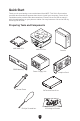

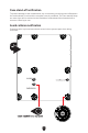


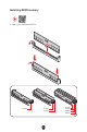
Table Of Contents
- Quick Start
- Specifications
- Special Features
- Package Contents
- Back Panel Connectors
- Overview of Components
- CPU Socket
- DIMM Slots
- PCI_E1~3: PCIe Expansion Slots
- M2_1~4: M.2 Slots (Key M)
- SATA_1~4 & SATA_A1~2: SATA 6Gb/s Connectors
- JAUD1: Front Audio Connector
- JFP1, JFP2: Front Panel Connectors
- CPU_PWR1~2, ATX_PWR1: Power Connectors
- JCI1: Chassis Intrusion Connector
- JUSB1: USB 3.2 Gen 2 Type-C Front Panel Connector
- JUSB2: USB 3.2 Gen 1 Connector
- JUSB3~4: USB 2.0 Connectors
- JTPM1: TPM Module Connector
- JOC_FS1: Safe Boot Jumper
- JDASH1 : Tuning Controller Connector
- CPU_FAN1, PUMP_FAN1, SYS_FAN1~5: Fan Connectors
- JBAT1: Clear CMOS (Reset BIOS) Jumper
- BAT1: CMOS Battery
- JRGB1: RGB LED Connector
- JARGB_V2_1~3: A-RAINBOW V2 (ARGB Gen2) LED Connectors
- Onboard LEDs
- Installing OS, Drivers & MSI Center
- UEFI BIOS

5
Case stand-off notification
To prevent damage to the motherboard, any unnecessary mounting stand-off between
the motherboard circuits and the computer case is prohibited. The Case standoff keep
out zone signs will be marked on the backside of motherboard (as shown below) to
serve as a warning to user.
Avoid collision notification
Protective paint is printed around each screw hole to prevent parts from being
scratched.