
User Manual
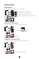
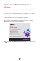
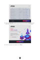
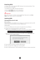
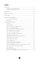
Table Of Contents
- Quick Start
- Specifications
- Special Features
- Package Contents
- Back Panel Connectors
- Overview of Components
- CPU Socket
- DIMM Slots
- PCI_E1~3: PCIe Expansion Slots
- M2_1~4: M.2 Slots (Key M)
- SATA_1~4 & SATA_A1~2: SATA 6Gb/s Connectors
- JAUD1: Front Audio Connector
- JFP1, JFP2: Front Panel Connectors
- CPU_PWR1~2, ATX_PWR1: Power Connectors
- JCI1: Chassis Intrusion Connector
- JUSB1: USB 3.2 Gen 2 Type-C Front Panel Connector
- JUSB2: USB 3.2 Gen 1 Connector
- JUSB3~4: USB 2.0 Connectors
- JTPM1: TPM Module Connector
- JOC_FS1: Safe Boot Jumper
- JDASH1 : Tuning Controller Connector
- CPU_FAN1, PUMP_FAN1, SYS_FAN1~5: Fan Connectors
- JBAT1: Clear CMOS (Reset BIOS) Jumper
- BAT1: CMOS Battery
- JRGB1: RGB LED Connector
- JARGB_V2_1~3: A-RAINBOW V2 (ARGB Gen2) LED Connectors
- Onboard LEDs
- Installing OS, Drivers & MSI Center
- UEFI BIOS

49
EZ Debug LED
These LEDs indicate the debug status of the motherboard.
Onboard LEDs
CPU - indicates CPU is not detected or fail.
DRAM - indicates DRAM is not detected or fail.
VGA - indicates GPU is not detected or fail.
BOOT - indicates the booting device is not detected or fail.
LED_SW1: EZ LED Control
This switch is used to switch on/ off all the LEDs of motherboard.
LED_SW1
LED_OFF
LED_ON
(Default)
JPWRLED1: LED power input
This connector is used by retailers to demonstrate onboard LED lights.
JPWRLED1 - LED power input