
User Manual
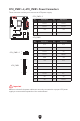

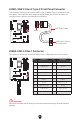
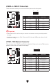
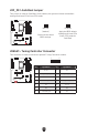
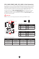
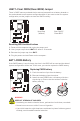
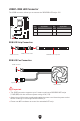
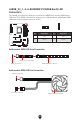
Table Of Contents
- Quick Start
- Specifications
- Special Features
- Package Contents
- Back Panel Connectors
- Overview of Components
- CPU Socket
- DIMM Slots
- PCI_E1~3: PCIe Expansion Slots
- M2_1~4: M.2 Slots (Key M)
- SATA_1~4 & SATA_A1~2: SATA 6Gb/s Connectors
- JAUD1: Front Audio Connector
- JFP1, JFP2: Front Panel Connectors
- CPU_PWR1~2, ATX_PWR1: Power Connectors
- JCI1: Chassis Intrusion Connector
- JUSB1: USB 3.2 Gen 2 Type-C Front Panel Connector
- JUSB2: USB 3.2 Gen 1 Connector
- JUSB3~4: USB 2.0 Connectors
- JTPM1: TPM Module Connector
- JOC_FS1: Safe Boot Jumper
- JDASH1 : Tuning Controller Connector
- CPU_FAN1, PUMP_FAN1, SYS_FAN1~5: Fan Connectors
- JBAT1: Clear CMOS (Reset BIOS) Jumper
- BAT1: CMOS Battery
- JRGB1: RGB LED Connector
- JARGB_V2_1~3: A-RAINBOW V2 (ARGB Gen2) LED Connectors
- Onboard LEDs
- Installing OS, Drivers & MSI Center
- UEFI BIOS

42
JUSB3~4: USB 2.0 Connectors
These connectors allow you to connect USB 2.0 ports on the front panel.
Important
Note that the VCC and Ground pins must be connected correctly to avoid possible
damage.
In order to recharge your iPad, iPhone and iPod through USB ports, please install
MSI Center utility.
Pin Signal Name Pin Signal Name
1 VCC 2 VCC
3 USB0- 4 USB1-
5 USB0+ 6 USB1+
7 Ground 8 Ground
9 No Pin 10 NC
1
2 10
9
JTPM1: TPM Module Connector
This connector is for TPM (Trusted Platform Module). Please refer to the TPM security
platform manual for more details and usages.
1
2 12
11
Pin Signal Name Pin Signal Name
1 SPI Power 2 SPI Chip Select
3
Master In Slave Out
(SPI Data)
4
Master Out Slave In
(SPI Data)
5 Reserved 6 SPI Clock
7 Ground 8 SPI Reset
9 Reserved 10 No Pin
11 Reserved 12 Interrupt Request