
User Manual
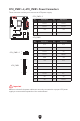

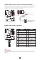
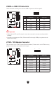
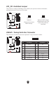
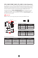
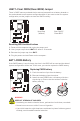
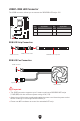
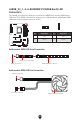

Table Of Contents
- Quick Start
- Specifications
- Special Features
- Package Contents
- Back Panel Connectors
- Overview of Components
- CPU Socket
- DIMM Slots
- PCI_E1~3: PCIe Expansion Slots
- M2_1~4: M.2 Slots (Key M)
- SATA_1~4 & SATA_A1~2: SATA 6Gb/s Connectors
- JAUD1: Front Audio Connector
- JFP1, JFP2: Front Panel Connectors
- CPU_PWR1~2, ATX_PWR1: Power Connectors
- JCI1: Chassis Intrusion Connector
- JUSB1: USB 3.2 Gen 2 Type-C Front Panel Connector
- JUSB2: USB 3.2 Gen 1 Connector
- JUSB3~4: USB 2.0 Connectors
- JTPM1: TPM Module Connector
- JOC_FS1: Safe Boot Jumper
- JDASH1 : Tuning Controller Connector
- CPU_FAN1, PUMP_FAN1, SYS_FAN1~5: Fan Connectors
- JBAT1: Clear CMOS (Reset BIOS) Jumper
- BAT1: CMOS Battery
- JRGB1: RGB LED Connector
- JARGB_V2_1~3: A-RAINBOW V2 (ARGB Gen2) LED Connectors
- Onboard LEDs
- Installing OS, Drivers & MSI Center
- UEFI BIOS

40
JCI1: Chassis Intrusion Connector
This connector allows you to connect the chassis intrusion switch cable.
Normal
(default)
Trigger the chassis
intrusion event
Using chassis intrusion detector
1. Connect the JCI1 connector to the chassis intrusion switch/ sensor on the chassis.
2. Close the chassis cover.
3. Go to BIOS > SETTINGS > Security > Chassis Intrusion Configuration.
4. Set Chassis Intrusion to Enabled.
5. Press F10 to save and exit and then press the Enter key to select Yes.
6. Once the chassis cover is opened again, a warning message will be displayed on
screen when the computer is turned on.
Resetting the chassis intrusion warning
1. Go to BIOS > SETTINGS > Security > Chassis Intrusion Configuration.
2. Set Chassis Intrusion to Reset.
3. Press F10 to save and exit and then press the Enter key to select Yes.