
User Manual
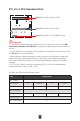
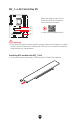

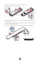
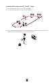
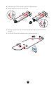
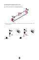
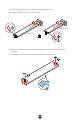
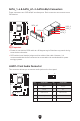
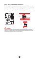
Table Of Contents
- Quick Start
- Specifications
- Special Features
- Package Contents
- Back Panel Connectors
- Overview of Components
- CPU Socket
- DIMM Slots
- PCI_E1~3: PCIe Expansion Slots
- M2_1~4: M.2 Slots (Key M)
- SATA_1~4 & SATA_A1~2: SATA 6Gb/s Connectors
- JAUD1: Front Audio Connector
- JFP1, JFP2: Front Panel Connectors
- CPU_PWR1~2, ATX_PWR1: Power Connectors
- JCI1: Chassis Intrusion Connector
- JUSB1: USB 3.2 Gen 2 Type-C Front Panel Connector
- JUSB2: USB 3.2 Gen 1 Connector
- JUSB3~4: USB 2.0 Connectors
- JTPM1: TPM Module Connector
- JOC_FS1: Safe Boot Jumper
- JDASH1 : Tuning Controller Connector
- CPU_FAN1, PUMP_FAN1, SYS_FAN1~5: Fan Connectors
- JBAT1: Clear CMOS (Reset BIOS) Jumper
- BAT1: CMOS Battery
- JRGB1: RGB LED Connector
- JARGB_V2_1~3: A-RAINBOW V2 (ARGB Gen2) LED Connectors
- Onboard LEDs
- Installing OS, Drivers & MSI Center
- UEFI BIOS

34
4. Insert your M.2 SSD into the M.2 slot at a 30-degree angle.
5. Rotate the EZ M.2 Clip to fix the M.2 SSD.
30º30º
30º30º
2280 SSD
2260 SSD
55
44
44
55
6. Remove the protective film from the thermal pad under the M.2 Shield Frozr
heatsink.
7. Put the M.2 Shield Frozr heatsink back in place and secure it.
77
66
77
77
77