
User Manual
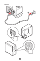
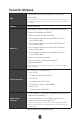
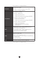
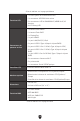
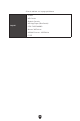
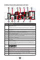
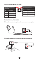
Table Of Contents
- Quick Start
- Specifications
- Special Features
- Package Contents
- Back Panel Connectors
- Overview of Components
- CPU Socket
- DIMM Slots
- PCI_E1~3: PCIe Expansion Slots
- M2_1~4: M.2 Slots (Key M)
- SATA_1~4 & SATA_A1~2: SATA 6Gb/s Connectors
- JAUD1: Front Audio Connector
- JFP1, JFP2: Front Panel Connectors
- CPU_PWR1~2, ATX_PWR1: Power Connectors
- JCI1: Chassis Intrusion Connector
- JUSB1: USB 3.2 Gen 2 Type-C Front Panel Connector
- JUSB2: USB 3.2 Gen 1 Connector
- JUSB3~4: USB 2.0 Connectors
- JTPM1: TPM Module Connector
- JOC_FS1: Safe Boot Jumper
- JDASH1 : Tuning Controller Connector
- CPU_FAN1, PUMP_FAN1, SYS_FAN1~5: Fan Connectors
- JBAT1: Clear CMOS (Reset BIOS) Jumper
- BAT1: CMOS Battery
- JRGB1: RGB LED Connector
- JARGB_V2_1~3: A-RAINBOW V2 (ARGB Gen2) LED Connectors
- Onboard LEDs
- Installing OS, Drivers & MSI Center
- UEFI BIOS

23
Connecteurs du panneau arrière
Élément Description
1
Bouton Clear CMOS
Éteignez votre ordinateur. Appuyez sur le bouton Clear CMOS pendant
5 à 10 secondes pour réinitialiser le BIOS aux valeurs par défaut.
2 DisplayPort
3 Ports USB 3.2 Gen 2 10 Gb/s Type-A (depuis CPU)
4 Port LAN (RJ45) 2,5 Gb/s
5 Ports USB 2.0 Type-A (depuis chipset B650)
6 Connecteurs d’antenne Wi-Fi
7 Ports audio
8
Bouton Flash BIOS
Veuillez vous référer à la page 58 pour la mise à jour du BIOS avec le
bouton Flash BIOS.
9
10 Port Flash BIOS
11 Ports USB 3.2 Gen 2 10 Gb/s Type-A (depuis chipset B650)
12 Port USB 3.2 Gen 2x2 20 Gb/s Type-C (depuis chipset B650)
13 Connecteur Sortie S/PDIF optique
11
77
22
55
44
66
88
99
1212
1313
33
1010 1111