Quick Start Thank you for purchasing the MSI® MEG X399 CREATION motherboard. This Quick Start section provides demonstration diagrams about how to install your computer. Some of the installations also provide video demonstrations. Please link to the URL to watch it with the web browser on your phone or tablet.
Installing a Processor https://youtu.
Installing DDR4 memory http://youtu.
Connecting the Front Panel Header http://youtu.
Installing the Motherboard 1 BAT1 2 If you want to use the mounting screw hole, please refer to M.2 SHIELD FROZR1 & M.2 SHIELD FROZR2 section for removing the M.2 SHIELD FROZR 2.
Installing SATA Drives http://youtu.
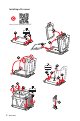
Installing a Graphics Card http://youtu.
Connecting Peripheral Devices 8 Quick Start
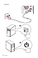
Connecting the Power Connectors http://youtu.
Power On 1 2 3 4 10 Quick Start
Contents Quick Start ............................................................................................................. 1 Preparing Tools and Components .......................................................................... 1 Installing a Processor ............................................................................................. 2 Installing DDR4 memory ........................................................................................ 3 Connecting the Front Panel Header ....
CPU_FAN1, PUMP_FAN1, SYS_FAN1~5, EXT_FAN1~3: Fan Connectors ............ 47 T_SEN1~3: Thermal Sensor Connectors ............................................................. 47 JCI1: Chassis Intrusion Connector ....................................................................... 48 JTPM1: TPM Module Connector ........................................................................... 48 JAUD1: Front Audio Connector ............................................................................
COMMAND CENTER ............................................................................................. 82 GAMING APP ......................................................................................................... 86 X-BOOST ............................................................................................................... 91 MYSTIC LIGHT ....................................................................................................... 93 MYSTIC LIGHT PARTY ..................
Safety Information y The components included in this package are prone to damage from electrostatic discharge (ESD). Please adhere to the following instructions to ensure successful computer assembly. y Ensure that all components are securely connected. Loose connections may cause the computer to not recognize a component or fail to start. y Hold the motherboard by the edges to avoid touching sensitive components.
Specifications CPU Supports AMD® Ryzen Threadripper processor for SocketTR4 Chipset AMD® X399 Chipset y 8x DDR4 memory slots, support up to 128GB* y Quad channel memory architecture** Memory y Supports DDR4 3600+(OC)/ 3466(OC)/ 3333(OC)/ 3200(OC)/ 3066(OC)/ 2933(OC)/ 2800(OC)/ 2667(OC)/ 2667(by JEDEC)/ 2400(by JEDEC)/ 2133(by JEDEC) MHz* * For the latest information about memory, please visit http://www.msi.com ** Please refer the DIMM Slots section for more details.
Continued from previous page y ASMedia® ASM3142 Chipset 1x USB 3.1 Gen2 (SuperSpeed USB 10Gbps) Type-C port available through the internal USB connector y AMD® X399 Chipset 1x USB 3.1 Gen1 (SuperSpeed USB) Type-A port on the back panel USB 1x USB 3.1 Gen1 (SuperSpeed USB) Type-C port on the back panel 4x USB 3.1 Gen1 (SuperSpeed USB) ports available through the internal USB connectors 4x USB 2.0 (High-speed USB) ports available through the internal USB connectors y AMD® CPU 8x USB 3.
Continued from previous page y 1x 24-pin ATX main power connector y 2x 8-pin ATX 12V power connector y 1x flat 4-pin ATX 12V power connector* y 8x SATA 6Gb/s connectors y 2x USB 2.0 connectors (supports additional 4 USB 2.0 ports) y 2x USB 3.1 Gen1 connectors (supports additional 4 USB 3.1 Gen1 ports) y 1x USB 3.
Continued from previous page I/O Controller NUVOTON NCT6797 Controller Chip y CPU/System temperature detection Hardware Monitor y CPU/System fan speed detection y CPU/System fan speed control Form Factor y EATX Form Factor y 12 in. x 10.7 in. (30.4 cm x 27.2 cm) y 1x 128 Mb flash BIOS Features y UEFI AMI BIOS y ACPI 6.0, SM BIOS 2.
Continued from previous page y Audio Boost 4 y Nahimic 3 y GAMING LAN with Gaming LAN Manager y Intel WiFi y Triple Turbo M.2 y Pump Fan y Smart Fan Control y Mystic Light y Mystic Light Extension y Mystic light SYNC y EZ DEBUG LED y DDR4 Steel Armor y M.2 Shield FROZR y PCI-E Steel Armor Special Features y Multi GPU – SLI Technology y Multi GPU – CrossFire Technology y DDR4 Boost y GAME Boost y Core Boost y Voice Boost y OC Engine (Clock gen) y USB with type A+C y AMD Turbo USB3.
JCORSAIR1 Connector Specification Supporting CORSAIR RGB Products Maximum connection Lighting PRO RGB LED Strip 20 HD RGB Fan 6 SP RGB Fan 6 LL RGB Fan 6 Package contents Please check the contents of your motherboard package. It should contain: y User Manual y Quick Installation Guide y Driver DVD y SATA 6G Cable x4 y LED Y CABLE y LED JCORSAIR CABLE y LED JRAINBOW CABLE y SENSOR CABLE x3 y M.2 Xpander-AERO y SLI HB BRIDGE M y WiFi antenna y Case Badge y HDD Sticker y VIP card y I/O Shielding y M.
Block Diagram 2/ 4 Channel DDR4 Memory Processor 3x M.2 PCI Express Bus 8x USB 3.1 Gen1 NV6797 Super I/O Realtek ALC1220 DMI 3.0 Audio Jacks PCIe x1 slot 8x SATA 6Gb/s PCIE Bus X399 Intel 9260 WiFi 4x USB 3.1 Gen1 2x USB 3.1 Gen1 4x USB 2.0 ASMEDIA ASM3142 PCIE Bus 1x USB 3.
Rear I/O Panel BIOS FLASHBACK+ port USB 3.1 Gen1 Type-A** WiFi Antenna Connectors LAN* Clear CMOS button USB 3.1 Gen1 Type-A*** BIOS FLASHBACK+ button Audio Ports** Optical S/PDIF-Out** USB 3.1 Gen1 Type-A** (VR READY ports) USB 3.1 Gen1 Type-C* USB 3.1 Gen1 Type-A* y Clear CMOS button - Power off your computer. Press and hold the Clear CMOS button for about 5-10 seconds to reset BIOS to default values. y BIOS FLASHBACK+ port/ button - Please refer to page 60 for Updating BIOS with BIOS FLASHBACK+.
Installing Antennas 1. Combine the antenna with the base. 2. Screw two antenna cables tight to the WiFi antenna connectors as shown. 2 1 3. Place the antenna as high as possible.
Realtek Audio Console After Realtek Audio Console is installed. You can use it to change sound settings to get better sound experience. Application Enhancement Advanced Settings Device Selection Main Volume Connector Settings Jack Status y Device Selection - allows you to select a audio output source to change the related options. The check sign indicates the devices as default.
Audio jacks to headphone and microphone diagram Audio jacks to stereo speakers diagram AUDIO INPUT Audio jacks to 7.
Overview of Components DIMMB2 DIMMB1 CPU_PWR1 DIMMA2 CPU_PWR2 CPU Socket CPU_FAN1 PUMP_FAN1 DIMMA1 JRGB2 T_SEN3 DIMMC1 SYS_FAN5 DIMMC2 SYS_FAN3 DIMMD1 JCORSAIR1 DIMMD2 ATX_PWR1 M2_3 JUSB3 JBLK_U1 SYS_FAN1 JBLK_D1 PCI_E1 JCI1 PCI_E2 JBAT1 PCI_E3 JUSB5 BAT1 JSLOW1 JUSB4 SATA▼1▲2 JOC_RT1 SATA▼3▲4 JOC_FS1 SATA▼5▲6 JRAINBOW1 PCI_E4 M2_1 M2_2 JPWRLED1 PCI_E5 JAUD1 SATA▼7▲8 SYS_FAN4 OC1 JRGB1 POWER1 RESET1 PCIE_PWR1 T_SEN1 T_SEN2 EXT_FAN1 EXT_FAN2 JUSB2 JUSB1 SYS_FAN2 JFP2 SYS_FAN3 JFP1 J
Component Contents Port Name Port Type Page CPU_FAN1, PUMP_FAN1, SYS_FAN1~5, EXT_FAN1~3 Fan Connectors 47 CPU_PWR1~2, ATX_PWR1, PCIE_PWR1 Power Connectors 44 CPU Socket Socket TR4 28 DIMMA1~DIMMD2 DIMM Slots 33 JAUD1 Front Audio Connector 49 JBAT1 Clear CMOS (Reset BIOS) Jumper 49 JBLK_U1, JBLK_D1 Base clock Plus, Minus connectors 50 JCI1 Chassis Intrusion Connector 48 JCORSAIR1 CORSAIR Connector 52 JFP1, JFP2 Front Panel Connectors 43 JOC_FS1 OC Force Enter BIOS Jumper 32
CPU Socket Please use the Torx screwdriver come with the AMD CPU and follow the steps below to install the CPU. 1 3 2 Video Demonstration Watch the video to learn how to unbox and install AMD Ryzen Threadripper CPU. https://youtu.be/yk4EpVUU03E 1. Loosen load plate screws with the AMD Torx screwdriver in the sequence 3→2→1. The load plate will automatically lift up to the fully open position. 1 3 AMD Torx screwdriver 2 2.
3. Remove the protective pin cap, and then close and buckle the frame rail. Protective pin cap 4. Close the load plate, and then turn the load plate screws clockwise a little with the AMD Torx screwdriver in the sequence 1→2→3→1→2→3 until they are snug. 1 AMD Torx screwdriver 3 2 5. Tighten load plate screws until you hear a click from the AMD Torx screwdriver. Important If the load plate is not secured properly, the computer will not power on. 6. Apply thermal paste on the top of the CPU.
7. Place the heatsink on the motherboard, align the bolts with the mounting nuts on the motherboard. Then, tighten the bolts in a diagonal order to spread the tension properly across the sides. 8. Finally, attach the CPU fan cable to the CPU fan connector on the motherboard. 2 4 3 1 Important y Always unplug the power cord from the power outlet before installing or removing the CPU. y Please retain the protective caps after installing the processor.
OC1: GAME BOOST Knob This knob allows you to manually select a stage from number 0 (default) to number 11 (extreme) for overclocking the processor. The processor’s voltage and frequency will be automatically adjusted after you power on your computer. GAME BOOST knob 0 2 10 1 1 1 8 4 6 Using GAME BOOST Knob To setup the GAME BOOST knob, take the following steps: 1. Set the GAME BOOST knob to hardware mode in BIOS Setup. 2. Power off the computer. 3.
4. Power on and then GAME BOOST will automatically overclock processor depending on the stage you selected. To disable GAME BOOST: 1. Set the GAME BOOST knob to HW mode in BIOS Setup. 2. Power off the computer. 3. Rotate the GAME BOOST knob to 0 and then power on. The configuration parameters will be returned to default values. Important y You can also control the GAME BOOST function in BIOS Setup or with MSI COMMAND CENTER software.
JSLOW1: Slow Mode Booting Jumper This jumper is used for LN2 cooling solution, that provides the extreme overclocking conditions, to boot at a stable processor frequency and to prevent the system from crashing. Normal (default) Enabled (Please enable this jumper during BIOS POST.) Important y Users will try extreme low temperature overclocking at their own risks. The overclocking results will vary according to the CPU version.
Memory module installation recommendation (For 2990WX processor only) D2 D1 C2 C1 CPU Socket A1 A2 B1 B2 1 DIMM 2 DIMMs SocketTR4 CPU 3 DIMMs (2990WX) 4 DIMMs 8 DIMMs DIMMA2 DIMMC2 DIMMC2 DIMMD2 DIMMB2 DIMMA2 DIMMC2 DIMMB2 DIMMA2 DIMMC1 DIMMC2 DIMMD1 DIMMD2 34 Overview of Components DIMMA2 DIMMB2 DIMMB1 DIMMA2 DIMMA1
Memory module installation recommendation (Except 2990WX processor) D2 D1 C2 C1 CPU Socket A1 A2 B1 B2 1 DIMM 2 DIMMs 3 DIMMs SocketTR4 CPU 4 DIMMs 8 DIMMs DIMMB2 DIMMD2 DIMMC2 DIMMD2 DIMMB2 DIMMA2 DIMMD2 DIMMB2 DIMMB2 DIMMA2 DIMMC1 DIMMC2 DIMMD1 DIMMD2 DIMMB2 DIMMB1 DIMMA2 DIMMA1 Overview of Components 35
PCI_E1~5: PCIe Expansion Slots BAT1 PCI_E1: PCIe 3.0 x16 PCI_E2: PCIe 2.0 x1 PCI_E3: PCIe 3.0 x8 PCI_E4: PCIe 3.0 x16 PCI_E5: PCIe 3.
PCI_E1 PCI_E1 PCI_E4 PCI_E4 PCI_E5 Important y If you install a large and heavy graphics card, you need to use a tool such as MSI Gaming Series Graphics Card Bolster to support its weight and to prevent deformation of the slot. y When adding or removing expansion cards, always turn off the power supply and unplug the power supply power cable from the power outlet. Read the expansion card’s documentation to check for any necessary additional hardware or software changes.
Installing SLI graphics cards For power supply recommendations for SLI configurations, please refer to the user guide of your graphics card to make sure you meet all the system requirements. To install SLI graphics cards: 1. Turn off your computer and disconnect the power cord, install two graphics cards into the PCI_E1 and PCI_E4 slots. 2. Connect the two cards together using the SLI Bridge Connector. 3. Connect all PCIe power connectors of the graphics cards. 4.
M2_1~3: M.2 Slots (Key M) Video Demonstration Watch the video to learn how to Install M.2 device. http://youtu.be/JCTFABytrYA M2_3 (Die 0) M2_1 (Die 1) * For 2990WX processor, M2_1 and M2_2 slots are controlled by Die1, and M2_3 is controlled by Die0. M2_2 (Die 1) M.2 SHIELD FROZR1 & M.2 SHIELD FROZR2 We provide the M.2 SHIELD FROZRs on the M.2 slots to help dissipate the heat away from the M.2 devices. Before installing M.2 devices, please remove the M.2 SHIELD FROZR 1 and M.
Installing M.2 device 1. Loosen the M.2 riser screw from the motherboard. 3. Insert your M.2 SSD into the M.2 slot at a 30-degree angle. 2. Move and fasten the M.2 riser screw to the appropriate location for your M.2 SSD. 4. Secure the M.2 SSD in place with the supplied M.2 screw. Supplied M.2 screw 3 4 2 30° 1 CAUTION For the installation of M2_2 slot with 22110 M.2 device, M2_1 slot with 2280 M.2 device or M2_3 slot with 2280 M.
Installing M.2 XPANDER-AERO card The M.2 XPANDER-AERO card provide four M.2 Key-M slots. To install the M.2 XPANDER-AERO card, please follows the steps below: 1. Remove the heatsink by loosening four heatsink screws on the bottom of M.2 XPENDER-AERO. 1 2. Loosen the M.2 screw from the base screw. 3. Loosen the base screw. 4. Move and fasten the base screw to the appropriate location for your M.2 device. 5. Insert your M.2 device into the M.2 slot at a 30-degree angle. 6. Secure the M.
9. Insert the M.2 XPENDER-AERO into an PCIe x16 slot (PCI_E1 or PCI_E4). 10. Use the screw to secure the M.2 XPENDER-AERO. 10 9 11. Connect the PCIE_PWR1 connector to the power supply. 12. Connect the case’s HDD LED cable to the JCASE connector. 13. Using the supplied HDD LED cable to connect the JMB connector and HDD LED pins (pin 1 & pin3) of JFP1.
SATA1~8: SATA 6Gb/s Connectors These connectors are SATA 6Gb/s interface ports. Each connector can connect to one SATA device. SATA8 SATA7 SATA6 SATA5 SATA4 SATA3 SATA2 SATA1 Important y Please do not fold the SATA cable at a 90-degree angle. Data loss may result during transmission otherwise. y SATA cables have identical plugs on either sides of the cable. However, it is recommended that the flat connector be connected to the motherboard for space saving purposes.
CPU_PWR1~2, ATX_PWR1, PCIE_PWR1: Power Connectors These connectors allow you to connect an ATX power supply. 1 12 24 ATX_PWR1 1 13 PCIE_PWR1 1 5 1 8 4 Ground CPU_PWR1/ CPU_PWR2 5 +12V 2 Ground 6 +12V 3 Ground 7 +12V 4 Ground 8 +12V 1 +3.3V 13 2 +3.3V 14 +3.3V -12V 3 Ground 15 Ground 4 +5V 16 PS-ON# 5 Ground 17 Ground 6 +5V 18 Ground 7 Ground 19 Ground 8 PWR OK 20 Res 9 5VSB 21 +5V 10 +12V 22 +5V 11 +12V 23 +5V 12 +3.
JUSB1~2: USB 2.0 Connectors These connectors allow you to connect USB 2.0 ports on the front panel. 2 10 1 9 1 VCC 2 VCC 3 USB0- 4 USB1- 5 USB0+ 6 USB1+ 7 Ground 8 Ground 9 No Pin 10 NC Important y Note that the VCC and Ground pins must be connected correctly to avoid possible damage. y In order to recharge your iPad,iPhone and iPod through USB ports, please install MSI® SUPER CHARGER utility. JUSB4~5: USB 3.1 Gen1 Connectors These connectors allow you to connect USB 3.
Charger Port The JUSB5 connector is a charger port which can increase USB power output for fast charging your smartphone or USB-powered devices. The Charger Port is hardware controlled by motherboard chip, it can still charge your device in suspend, hibernate state or even shutdown states. However, when you boot the computer into Windows®, you will need to install the MSI® SUPER CHARGER application to turn ON/OFF the Charging mode.
CPU_FAN1, PUMP_FAN1, SYS_FAN1~5, EXT_FAN1~3: Fan Connectors Fan connectors can be classified as PWM (Pulse Width Modulation) Mode or DC Mode. PWM Mode fan connectors provide constant 12V output and adjust fan speed with speed control signal. DC Mode fan connectors control fan speed by changing voltage. This motherboard can automatically detect PWM and DC mode. However, you can follow the instruction below to adjust the fan connector to PWM or DC Mode manually.
JCI1: Chassis Intrusion Connector This connector allows you to connect the chassis intrusion switch cable. Normal (default) Trigger the chassis intrusion event Using chassis intrusion detector 1. Connect the JCI1 connector to the chassis intrusion switch/ sensor on the chassis. 2. Close the chassis cover. 3. Go to BIOS > SETTINGS > Security > Chassis Intrusion Configuration. 4. Set Chassis Intrusion to Enabled. 5. Press F10 to save and exit and then press the Enter key to select Yes. 6.
JAUD1: Front Audio Connector This connector allows you to connect audio jacks on the front panel. 2 10 1 9 1 MIC L 2 Ground 3 MIC R 4 NC 5 Head Phone R 6 MIC Detection 7 SENSE_SEND 8 No Pin 9 Head Phone L 10 Head Phone Detection JBAT1: Clear CMOS (Reset BIOS) Jumper There is CMOS memory onboard that is external powered from a battery located on the motherboard to save system configuration data. If you want to clear the system configuration, set the jumper to clear the CMOS memory.
JBLK_U1, JBLK_D1: Base clock Plus, Minus connectors You can use these connectors to connect the external buttons. Press the button connecting to JBLK_U1 to increase the CPU base clock or press the button connecting to JBLK_D1 to decrease the CPU base clock. JBLK_D1 (short the jumper to decrease the CPU base clock) JBLK_U1 (short the jumper to increase the CPU base clock) POWER1, RESET1: Power Button, Reset Button Re s et The Power / Reset button allows you to power on / reset the computer.
JRGB1, JRGB2, JRAINBOW1: RGB LED connectors The JRGB1/ JRGB2 connector allows you to connect the 5050 RGB LED strips 12V. The JRAINBOW1 connector allows you to connect the WS2812B Individually Addressable RGB LED strips 5V.
JCORSAIR1: CORSAIR Connector The JCORSAIR1 connector allows you to connect the CORSAIR Individually Addressable Lighting PRO RGB LED strips 5V or CORSAIR RGB fans with the CORSAIR fan hub. Once all items are connected properly, you can control the CORSAIR RGB LED strips and fans with MSI's software.
Onboard LEDs EZ Debug LED These LEDs indicate the debug status of the motherboard. CPU - indicates CPU is not detected or fail. DRAM - indicates DRAM is not detected or fail. VGA - indicates GPU is not detected or fail. BOOT - indicates the booting device is not detected or fail. DIMM LEDs These LED indicate the memory modules are installed. DIMM LEDs Fan LEDs These LEDs indicate the fan control mode.
JPWRLED1: LED light demonstration power input connector This connector is used by retailers to demonstrate onboard LED lights. JPWRLED1 - LED power input Debug Code LED The Debug Code LED displays progress and error codes during and after POST. Refer to the Debug Code LED table for details.
Debug Code LED Table 34 CPU post-memory initialization. Application Processor(s) (AP) initialization SEC Progress Codes 01 Power on. Reset type detection (soft/ hard) 35 CPU post-memory initialization. Boot Strap Processor (BSP) selection 02 AP initialization before microcode loading 36 CPU post-memory initialization.
94 PCI Bus Enumeration 32 95 PCI Bus Request Resources 96 PCI Bus Assign Resources 97 Console Output devices connect PCI resource allocation error.
ACPI States Codes The following codes appear after booting and the operating system into ACPI modes.
BIOS Setup The default settings offer the optimal performance for system stability in normal conditions. You should always keep the default settings to avoid possible system damage or failure booting unless you are familiar with BIOS. Important y BIOS items are continuously update for better system performance. Therefore, the description may be slightly different from the latest BIOS and should be for reference only. You could also refer to the HELP information panel for BIOS item description.
Resetting BIOS You might need to restore the default BIOS setting to solve certain problems. There are several ways to reset BIOS: y Go to BIOS and press F6 to load optimized defaults. y Short the Clear CMOS jumper on the motherboard. Important Be sure the computer is off before clearing CMOS data. Please refer to the Clear CMOS jumper section for resetting BIOS.
Updating BIOS with BIOS FLASHBACK+ Before updating: Please download the latest BIOS file that matches your motherboard model from MSI® website and rename the BIOS file to MSI.ROM. And then, save the MSI.ROM file to the root of USB flash drive. Important Only the FAT32 format USB flash drive supports updating BIOS by BIOS FLASHBACK+. 1. Connect power supply to CPU_PWR1,CPU_PWR2 and ATX_PWR1. (No other components are necessary but power supply.) 2. Plug the USB flash drive that contains the MSI.
EZ Mode At EZ mode, it provides the basic system information and allows you to configure the basic setting. To configure the advanced BIOS settings, please enter the Advanced Mode by pressing the Setup Mode switch or F7 function key.
y Information display - click on the CPU, Memory, Storage, Fan Info and Help buttons on left side to display related information. y Function buttons - enable or disable the LAN Option ROM, HD audio controller, AHCI/RAID, CPU Fan Fail Warning Control, Windows 10 WHQL support and BIOS Log Review by clicking on their respective button. Hardcore Mode - always keep the CPU in full speed mode to maximize system performance. This feature will increase power consumption.
Advanced Mode Press Setup Mode switch or F7 function key can switch between EZ Mode and Advanced Mode in BIOS setup. A-XMP switch Setup Mode switch Screenshot Search Language System information GAME BOOST switch Boot device priority bar BIOS menu selection BIOS menu selection Menu display y GAME BOOST switch/ A-XMP switch/ Setup Mode switch/ Screenshot/ Favorites/ Language/ System information/ Boot device priority bar - please refer to the descriptions of EZ Mode Overview section.
SETTINGS System Status f System Date Sets the system date. Use tab key to switch between date elements. The format is . Day of the week, from Sun to Sat, determined by BIOS. Read-only. The month from Jan. through Dec. The date from 1 to 31 can be keyed by numeric function keys. The year can be adjusted by users. f System Time Sets the system time. Use tab key to switch between time elements. The time format is .
fAbove 4G memory/ Crypto Currency mining [Disabled] Enables or disables 64-bit capable devices to be decoded in above 4G address space. It is only available if the system supports 64-bit PCI decoding. [Enabled] Allows you to utilize more than 4x GPUs. [Disabled] Disables this function. fPCIe SlotX Lanes Configuration PCIe lanes configuration for MSI M.2 XPANDER series cards/ Other M.2 PCIe storage card. f ACPI Settings Sets ACPI parameters of onboard power LED behaviors. Press Enter to enter the submenu.
fSATA Mode [AHCI Mode] Sets the operation mode of the onboard SATA controller. [AHCI Mode] Specify the AHCI mode for SATA storage devices. AHCI (Advanced Host Controller Interface) offers some advanced features to enhance the speed and performance of SATA storage device, such as Native Command Queuing (NCQ) and hot-plugging. [RAID Mode] Enables RAID function for SATA storage devices. fSATAx Hot Plug [Disabled] Allows user to enable or disable the SATA hot plug support.
fSystem Power Fault Protection [Disabled] Enables or disables the system to boot up when detecting abnormal voltage input. [Enabled] Protect the system from unexpected power operating and remain the shut down status. [Disabled] Disables this function. f Windows OS Configuration Sets Windows detailed configuration and behaviors. Press Enter to enter the submenu. fWindows 10 WHQL Support [Disabled] Enables the supports for Windows 10 or disables for other operating systems.
fResume by USB Device [Disabled] Disables or enables system wake up from S3/S4 by USB device. [Enabled] Enables the system to be awakened from sleep state when activity of USB device is detected. [Disabled] Disables this function. fResume From S3/S4/S5 by PS/2 Mouse [Disabled] Enables or disables the system wake up by PS/2 mouse. [Enabled] Enables the system to be awakened from S3/ S4/ S5 state when activity of PS/2 mouse is detected. [Disabled] Disables this function.
f POST Beep [Disabled] Enables or disables POST beep. f AUTO CLR_CMOS [Disabled] Enables or disables the CMOS data to be resumed automatically when the system cannot boot to OS and reboot repeatedly. f Boot Mode Select [LEGACY+UEFI] Sets the system boot mode from legacy or UEFI architecture depending on OS installation requirement. This item will become un-selectable and will be configured automatically by BIOS when Windows 10 WHQL Support is enabled.
f Trusted Computing Sets TPM (Trusted Platform Module) function. fSecurity Device Support [Disabled] Enables or disables the TPM function to build the endorsement key for accessing the system. fAMD fTPM switch [AMD CPU fTPM] Selects TPM device. [AMD CPU fTPM] Select it for AMD Firmware TPM. [AMD CPU fTPM Disabled] Select it for Discrete TPM. fDevice Select [Auto] Sets the version of the TPM device. The version must be identical with the device. Sets to Auto, system will detect the TPM2.0 or TPM1.
OC Important y Overclocking your PC manually is only recommended for advanced users. y Overclocking is not guaranteed, and if done improperly, it could void your warranty or severely damage your hardware. y If you are unfamiliar with overclocking, we advise you to use GAME BOOST function for easy overclocking. f OC Explore Mode [Normal] Enables or disables to show the normal or expert version of OC settings. [Normal] [Expert] Provides the regular OC settings in BIOS setup.
f CPU Base Clock (MHz) [Default] Sets the CPU Base clock. You may overclock the CPU by adjusting this value. Please note that overclocking behavior and stability is not guaranteed. This item appears when a CPU that support this function is installed. f A-XMP [Disabled] Please enable A-XMP or select a profile of memory module for overclocking the memory. This item will be available when the installed memory modules, processor and motherboard support this function.
fDRAM CH_A/B / CH_C/D Over Current Protection [Auto] Sets the current limit for DRAM over-current protection. If set to Auto, BIOS will configure this setting automatically. [Auto] This setting will be configured automatically by BIOS. [Enhanced] Extends the current range for over-current protection. fDRAM CH_A/B / CH_C/D Switching Frequency [Auto] Sets the PWM working speed to stabilize DRAM voltage and minimize ripple range. Increasing the PWM working speed will cause higher temperature of MOSFET.
fDIMMx Memory SPD Press Enter to enter the sub-menu. The sub-menu displays the information of installed memory. Read only. f CPU Features Press Enter to enter the sub-menu. fSMT Mode [Auto] Enables/ disables the AMD Simultaneous Multi-Threading. This item appears when the installed CPU supports this technology. fGlobal C-state Control [Auto] Enables/ disables IO based C-state generation and DF C-states. fOpcache Control [Auto] Enables/ disables Opcache.
fSVM Mode [Enabled] Enables/ disables the AMD SVM (Secure Virtual Machine) Mode. fPrecision Boost Overdrive [Auto] Enables/ disables the precision boost overdrive for CPU. If set to Auto, BIOS will configure these settings. fPrecision Boost Overdrive Scalar [Auto] Sets the scalar of precision boost overdrive. If set to Auto, BIOS will configure these settings.
M-FLASH M-FLASH provides the way to update BIOS with a USB flash drive. Please down-load the latest BIOS file that matches your motherboard model from MSI website, save the BIOS file into your USB flash drive. And then follow the steps below to update BIOS. 1. Insert the USB flash drive that contains the update file into the computer. 2. Click on M-FLASH tab, a demand message will be prompted. Click on Yes to reboot and enter the flash mode. 3.
OC PROFILE f Overclocking Profile 1/ 2/ 3/ 4/ 5/ 6 Overclocking Profile 1/ 2/ 3/ 4/ 5/ 6 management. Press to enter the submenu. fSet Name for Overclocking Profile 1/ 2/ 3/ 4/ 5/ 6 Name the current overclocking profile. fSave Overclocking Profile 1/ 2/ 3/ 4/ 5/ 6 Save the current overclocking profile. fLoad Overclocking Profile 1/ 2/ 3/ 4/ 5/ 6 Load the current overclocking profile. fClear Overclocking Profile 1/ 2/ 3/ 4/ 5/ 6 Clear the current overclocking profile.
Software Description Please download and update the latest utilities and drivers at www.msi.com Installing Windows® 10 1. Power on the computer. 2. Insert the Windows® 10 disc into your optical drive. 3. Press the Restart button on the computer case. 4. Press F11 key during the computer POST (Power-On Self Test) to get into Boot Menu. 5. Select your optical drive from the Boot Menu. 6. Press any key when screen shows Press any key to boot from CD or DVD... message. 7.
APP MANAGER APP MANAGER is a handy management application for integration of MSI applications and software interface. Providing easy shortcut entrance and real-time update information of all the MSI software and applications. APP list Total Install/ Update Motherboard Information y APP list - shows all the applications and software be supported by this motherboard. An icon represents a entrance to the application.
LIVE UPDATE 6 LIVE UPDATE 6 is an application for the MSI® system to scan and download the latest drivers, BIOS and utilities. With LIVE UPDATE 6, you don’t need to search the drivers on websites, and don’t need to know the models of motherboard and graphics cards. LIVE UPDATE 6 will download the appropriate drivers automatically.
1. Select the Live Update tab. 2. Choose Automatic scan, system will automatically scan all the items and search for the latest update files. Or you can choose Manual scan and select the items you wish to scan. 3. Click the Scan button at the bottom. It may take several moments to complete the process. 4. When the download list appears, please select the items you intend to update. 5. Click Download button at the bottom. 6. When Save Path prompt, you can specify a download directory. 7.
COMMAND CENTER COMMAND CENTER is an user-friendly software and exclusively developed by MSI, helping users to adjust system settings and monitor status under OS. With the help of COMMAND CENTER, making it possible to achieve easier and efficient monitoring process and adjustments than that under BIOS. In addition, the COMMAND CENTER can be a server for mobile remote control application.
CPU Fan CPU Fan control panel provides Smart mode and Manual Mode. You can switch the control mode by clicking the Smart Mode and Manual Mode buttons on the top of the CPU Fan control panel. y Manual Mode - allows you to manually control the CPU fan speed by percentage. y Smart Mode - a linear fan speed control feature. The control panel contains 4 dots allows you to drag and adjust the Smart Speed slopes. The fan speed will be changed along these lines with CPU temperature.
Option Buttons - Advanced When click the Advanced button, The Voltage, Fan and DRAM icons will appear. y Voltage - allows you to adjust advanced voltage values of CPU and chipset. y Fan - allows you to control the system fans speed. y DRAM - shows the current Advanced DRAM parameters, and allows you to change the settings by selecting values from the drop-down menu on the right hand side. y Sensor - allows you to monitor your motherboard temperature and fan speed with the virtual thermal image.
y Warning - contains fields of voltage, fan speed and temperature for you to set the threshold values. When system detects the status over your settings, a warning message will pop-up. y Mobile Control - is only available for the motherboard with the built-in WiFi module. It allows you to enable/disable the COMMAND CENTER Remote Server. Please refer to the instruction on the Mobile Control control panel. y To start remote control: (optional) 1.
GAMING APP GAMING APP is an application designed to quickly control your system for improving gaming performance. Setting Button Remote Control Setting Button Cooler Boost CPU Frequency Information Button Gaming Function Buttons GPU Frequency Control Mode Buttons Peripheral Device Function Buttons y Setting Button - allows you to choose running GAMING APP when Windows starts or let GAMING APP to overwrite the VGA fan control function. y Information Button - shows the information of this application.
Eye Rest Eye Rest allows you to optimize the display on your monitor. y EyeRest - reduces blue-light of your LED backlit screen, in order to protect your eyes. y Gaming - automatically increase contrast ratio of your screen. y Movie - automatically increase dynamic contrast ratio of your screen. y Customize - allows you to adjust gamma, contrast and color balance for your screen. y Default - loads the default settings.
Gaming Hotkey Gaming Hotkey provides instant control of the system through user defined hotkeys. Categories Toggle Gaming Hotkey ON/OFF Hotkey Manager Current Hotkeys y Gaming Hotkey ON/OFF - allows you to turn ON/OFF the Gaming Hotkey function. y Categories Toggle - allows you to toggle over the Hotkey categories. Macro Genie - provides the keyboard and mouse macro record function and allows you to define the hotkeys for the macro recorder. 1.
Mouse Master Mouse Master provides mouse macro function. You can also use it to change DPI of your mouse. Delay Time Macro Hot Key Mouse Action Action List Edit Buttons Load Button DPI Setting Default Button DPI Hot Key Test Area Clear Button Save Button y Delay Time - allows you to apply a delay time in mouse macro. y Macro Hot Key - allows you to assign a hotkey from A to Z to activate the macro. y Mouse Action - assigns mouse actions to the macro.
VR Ready It will optimize the performance of your system to ensure everything is VR Ready. VR ON/ OFF Applications y VR ON/ OFF -enables or disables VR settings. y Applications - appears when you turn on the VR support. It allows you to close some applications to optimize the system for better VR experience. Voice Boost Voice Boost function allows you to boost volume in voice communication tools. ON/ OFF toggle VoIP Selection VoIP Setting y ON/ OFF toggle -enables or disables Voice Boost function.
X-BOOST The MSI X-BOOST allows you to select the system performance mode to meet your current system environment or support faster storage access speed for your external storage or memory cards. Easy In Easy page, you can select one system performance mode to meet the current system environment. Setting Performance mode Performance information y Performance mode - moves over the mouse to any one of performance mode and click on the ON button to enable it.
Advance In Advance page, you can enable the USB SPEED UP, the STORAGE BOOST and VR BOOST. Setting Device information y Device information - displays the information and current transfer rates/ access speeds of USB/ storage devices. y Setting - enables or disables Run X-BOOST when windows starts. y USB SPEED UP - supports faster data transfer rates of the USB storage devices. y STORAGE BOOST - supports faster access speed of storage device.
MYSTIC LIGHT MYSTIC LIGHT is an application allows you to control LED lights of MSI products. For some earlier products, you can go to product download page to download the applicable LED control software. Main Screen The Main screen is used to configure what devices need to be synchronized and LED light effect options.
You can also change settings for single device. To do that, you have to click the sync bubble twice and make it turn gray as below. Then you go to DEVICE SETTING and click SETTING. click SETTING After that, the computer will open a different windows and you can modify LED there individually. Note: The motherboard picture and name may vary according to different models. You can save the current settings by clicking Save. Individual - Default: All the Sync device bubble would appear black.
If you wish to customize multiple device at the same time, click the bubble until it turn red like below. Use the LIGHT EFFECT & COLOR section on the main menu to make change. Note: Currently only GTX 1080 Ti Lightning -/X/Z and GTX 1080 Ti Gaming -/X Trio supports Light Speed/Brightness and no device supports Direction. Profile01~03 - Save Sync profile settings. y Save Button - saves sync device settings and lighting effect settings to the current Sync Profile.
Motherboard Screen The motherboard screen is used to configure the LED light effect of the motherboard. SYNC ALL Return Button ON/ OFF ALL LED Motherboard Name PROFILE LED AREA Apply Button Save Button Live Preview Light Effect Options Note: The motherboard picture and name may vary according to different models. y Return Button - returns to the main screen. y ON/OFF ALL LED - allows you to turn ON/ OFF all LED lights of the motherboard.
MYSTIC LIGHT PARTY This section allows you to control LED across different platform. The pre-requisite is that the platforms should all be connected within the same local network. Refer to device support list web page. https://www.msi.com/Landing/Mystic-Light-Party. PARTY Upon clicking PARTY, this window would pop out. On your master platform, click + to create a host group.
The group has been created. The other computers in the same local network are able to join the group with MYSTIC LIGHT software. DELETE Group Button Control Group Button Invitation Status Indicator Group In/Out Status DELETE Group Button - deletes the group. Control Group Button - enters the group control panel. Invitation Status Indicator - appears when receive an invitation to a group. Group In/Out Status - shows Group In/Out status.
Group Control Panel If everything is set up properly, you can see your slave platform on master platform MYSTIC LIGHT PARTY window. APPLY button Light Effect Options Invite Button Color Selection Group Members Icon At the panel below, you may apply different LED settings and color to the selected platform.
y Invite Button - enters the INVITE screen. y Light Effect Options - allow you to customize lighting effect. Off Always on Breathe Flash Double flash Random Marquee Rainbow Sound beat y Color Selection - allows you to change color. Inviting Member Click the Invite button in the Group Control Panel to enter the INVITE screen. Select the device you want to invite and click the INVITE button.
SMART TOOL SMART TOOL is a convenient tool that can help you to create your Windows installation USB flash drive, and it can also create a super RAID. Main menu After installing and activating SMART TOOL, it will display a main menu for you to choose Smart Tool or SUPER RAID. Note that the SUPER RAID is only available when your system equipped with at least 3 hard-disk drives (1 system disk and 2 data disks).
SUPER RAID This utility allows you to create a super RAID in Windows system. To create a super RAID: 1. Use checkboxs to select the disks you want included in your RAID. 2. Choose Speed Up or Backup for RAID type. y Speed Up = RAID0 y Backup = RAID1 3. Click Start. 4. When prompt Finish!, click OK. Important SUPER RAID can't includ the system disk.
RAMDISK RAMDISK creates a virtual RAM drive using the available memory in your computer, the performance of the RAMDISK is faster than an SSD and hard drive. RAMDISK allows you to store any temporary information on it. Furthermore, using the RAMDISK will extend your SSD’s life by sparing it from excessive reading and writing. Creating a RAM Disk When RAMDISK is started, it will create a default RAM disk. If you want to change settings, refer to following instructions.
GAMING LAN MANAGER GAMING LAN MANAGER is an utility for traffic shaping for the Windows 10. It can keep your internet fast during heavy upload/ download and improve your ping for online games. If your motherboard has a Wi-Fi module, GAMING LAN MANAGER provides virtual access point function for traffic shaping for your mobile devices. y Applications - displays currently using network bandwidth applications. You can prioritize Games, Medias or File sharing programs as high as possible.
Configuring Bandwidth This section describes how to configure Internet Provider Speed. You can configure default internet upload and download bandwidth from the Network Test tab on the GAMING LAN MANAGER window. Important Before using the GAMING LAN MANAGER for the first time, you should use the Test Network Speed button which runs a speed test of your current total Internet bandwidth delivered through your Internet service provider.
Nahimic 3 Nahimic 3 is designed to offer the best audio experience it contains audio effects, microphone effects and Sound Tracker. Installation and Update Nahimic 3 is included in the audio driver. If you need to install it or update it, please use the Driver Disc with your motherboard or download the driver from MSI’s official website. Audio Tab From this tab, you can access all of Nahimic 3’s audio effects, audio profiles and settings.
Voices - it boosts (or removes) the speech in movies, video games and incoming communication from -12 to +12 dB. Bass - increases (or decreases) the energy in low frequencies from -12 to +12 dB. Treble - increases (or decreases) the energy in high frequencies from -12 to +12 dB. y Reset Button - restores the current profile to its default values. y Try Button - launches an audio sample that allows to test audio settings.
Sound Tracker Tab The Sound Tracker is an FPS oriented feature that provides a visual indication localizing the sources of the sounds while in a game. These are represented by dynamic segments pointing the direction of the sounds: the more opaque they are, the stronger the sounds are. Thanks to this feature, players are able to pick up an approaching threat more definitively and easily, thereby being even more dynamic. The Sound Tracker captures the 5.1 and 7.
Troubleshooting Before sending the motherboard for RMA repair, try to go over troubleshooting guide first to see if your got similar symptoms as mentioned below. The power is not on. y Connect the AC power cord to an electrical outlet securely. y Check if all ATX power connectors like ATX_PWR1, CPU_PWR1, CPU_PWR2 are connected from the power supply to the motherboard? y Some power supply units have a power button on the rear side, make sure the button is turned on.
Regulatory Notices C-Tick Compliance FCC Compliance Statement Note: This equipment has been tested and found to comply with the limits for a Class B digital device, pursuant to part 15 of the FCC Rules. These limits are designed to provide reasonable protection against harmful interference in a residential installation.
be discarded as municipal wastes anymore, and manufacturers of covered electronic equipment will be obligated to take back such products at the end of their useful life. MSI will comply with the product take back requirements at the end of life of MSI-branded products that are sold into the EU. You can return these products to local collection points.
EC platné od 13. srpna 2005 je zakázáno likvidovat “elektrické a elektronické výrobky” v běžném komunálním odpadu a výrobci elektronických výrobků, na které se tato směrnice vztahuje, budou povinni odebírat takové výrobky zpět po skončení jejich životnosti. Společnost MSI splní požadavky na odebírání výrobků značky MSI, prodávaných v zemích EU, po skončení jejich životnosti. Tyto výrobky můžete odevzdat v místních sběrnách.
产品中有害物质的名称及含量 部件名称 铅 (Pb) 汞 (Hg) 镉 (Cd) 印刷电路板组件* ╳ ○ 电池** ╳ 外部信号连接头 ╳ 线材 本表格依据 SJ/T 11364 的规定编制。 ╳ 有害物质 六价铬 (Cr(VI)) 多溴联苯 (PBB) 多溴二苯醚 (PBDE) ○ ○ ○ ○ ○ ○ ○ ○ ○ ○ ○ ○ ○ ○ ○ ○ ○ ○ ○ ○: 表示该有害物质在该部件所有均质材料中的含量均在 GB/T 26572 规定的限量要求以下。 ╳: 表示该有害物质至少在该部件的某一均质材料中的含量超出 GB/T 26572 规定的限量要求,但所有部件都符合 欧盟RoHS要求。 * 印刷电路板组件: 包括印刷电路板及其构成的零部件。 ** 电池本体上如有环保使用期限标识,以本体标识为主。 ■ 上述有毒有害物质或元素清单会依型号之部件差异而有所增减。 ■ 產品部件本体上如有环保使用期限标识,以本体标识为主。 限用物質含有情況標示聲明書 單元 限用物質及其化學符號 鉛 (Pb) 汞 (Hg) 鎘 (Cd) 電路板 ○