
Computer Computer Hardware User Manual


2-13
Hardware Setup
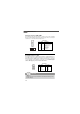
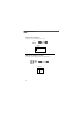
Fan Power Connectors: CPUFAN1, SYSFAN1
The fan power connectors support system cooling fan with +12V. When connecting
the wire to the connectors, always take note that the red wire is the positive and
should be connected to the +12V, the black wire is Ground and should be connected
to GND. If the mainboard has a System Hardware Monitor chipset on-board, you must
use a specially designed fan with speed sensor to take advantage of the CPU fan
control.
Important
Please refer to the recommended CPU fans at VIA’s official website or consult
the vendors for proper CPU cooling fan.
SENSOR
CPUFAN1
+12V
GND
SENSOR
SYSFAN1
+12V
GND
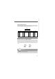
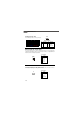
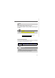
Parallel Port Header: JLPT1
The mainboard provides a 26-pin header for connection to an optional parallel port
bracket. The parallel port is a standard printer port that supports Enhanced Parallel
Port (EPP) and Extended Capabilities Parallel Port (ECP) mode.
PIN SIGNAL PIN SIGNAL
1 RSTB# 2 AFD#
3 PRND0 4 ERR#
5 PRND1 6 PINIT#
7 PRND2 8 LPT_SLIN#
9 PRND3 10 GND
11 PRND4 12 GND
13 PRND5 14 GND
PIN SIGNAL PIN SIGNAL
15 PRND6 16 GND
17 PRND7 18 GND
19 ACK# 20 GND
21 BUSY 22 GND
23 PE 24 GND
25 SLCT 26 GND
2
1
26
25
JLPT1