
Computer Computer Hardware User Manual


2-10
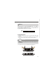
MS-9802 Mainboard
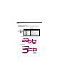
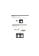
Front Panel Connector: JFP1
The mainboard provides one front panel connector for electrical connection to the
front panel switches and LEDs. The JFP1 is compliant with Intel
®
Front Panel I/O
Connectivity Design Guide.
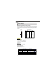
External circuit
0.1uf
WDTO#
0 ohm
FP_RST#
4.7K ohm
VCC3
Reset Circuit
1
2
9
10
JFP1
HDD
LED
Reset
Switch
Power
LED
Power
Switch
+
-
-
+
+
-
PIN SIGNAL DESCRIPTION
1 HD_LED + Hard disk LED pull-up
2 FP PWR/SLP MSG LED pull-up
3 HD_LED - Hard disk active LED
4 FP PWR/SLP MSG LED pull-up
5 RST_SW - Reset Switch low reference pull-down to GND
6 PWR_SW + Power Switch high reference pull-up
7 RST_SW + Reset Switch high reference pull-up
8 PWR_SW - Power Switch low reference pull-down to GND
9 RSVD_DNU Reserved. Do not use.
JFP1 Pin Definition
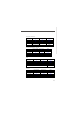
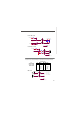
200 ohm
VCC3
VCC3
4.7K ohm
HDDLED#
D
12
3
External circuit
4.7K ohm
VCC3
SATALED#
IDEACTP#
LED
12
HDD LED Circuit