
Installation Instruction Manual


INSTALLATION INSTRUCTIONS 7
M S D • W W W . M S D P E R F O R M A N C E . C O M • ( 9 1 5 ) 8 5 7 - 5 2 0 0 • F A X ( 9 1 5 ) 8 5 7 - 3 3 4 4
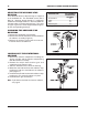
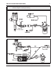
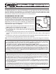
Figure 12 Wiring the Ready-to-Run Distributor.
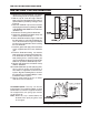
Figure 13 Wiring to an MSD Ignition Control.
WARNING: High voltage is present on the coil terminals. Do not touch the terminals or coil tower
when the engine is cranking or running.
GRAY TO
TACH INPUT
GRAY TO
TACH INPUT