
Installation Instruction Manual
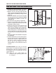

6 INSTALLATION INSTRUCTIONS
M S D • W W W . M S D P E R F O R M A N C E . C O M • ( 9 1 5 ) 8 5 7 - 5 2 0 0 • F A X ( 9 1 5 ) 8 5 7 - 3 3 4 4
VACUUM ADVANCE LOCKOUT
If you do not want to use the vacuum advance
canister of the PN 8543 or PN 8544, MSD has
supplied a lockout mechanism.
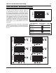
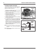
1. Remove the two Allen head screws that hold
the advance canister (Figure 10).
2. Remove the snap ring that holds the magnetic
pickup assembly in place.
3. Gently lift up on the mag pickup plate and slide
the vacuum canister out.
4. Install the Lockout Plate in place of the canister.
Install the two retaining screws.
5. Install the supplied screw and washer through
the Lockout and tighten.
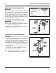
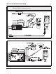
6. It is important to make sure the pickup plate
is parallel with the housing of the distributor
(Figure 11). If it is co cked or sla nted, the
paddles of the reluctor may contact the pickup.
Check the clearance by rotating the distributor
shaft. If necessary, use the supplied shims
under the Lockout hold-down to correctly
position the pickup plate.
Note: If no shims were required, use one beneath
the washer of the Lock-Out Hold Down
Screw.
Note: Do not forget to plug the original vacuum
advance hose.
Figure 11 Checking Installation of the Lockout Plate.
Figure 10 Removing the Vacuum Canister.
RELUCTOR
PADDLES
CANISTER
SCREWS
MAG PICKUP
PLATE
SNAP
RING