
Installation Instruction Manual

INSTALLATION INSTRUCTIONS 5
M S D • W W W . M S D P E R F O R M A N C E . C O M • ( 9 1 5 ) 8 5 7 - 5 2 0 0 • F A X ( 9 1 5 ) 8 5 7 - 3 3 4 4
OPTIONAL VACUUM ADVANCE LOCKOUT
If you do not want to use the vacuum advance canister
of the MSD Distributor, MSD has supplied the distributor
with a lockout mechanism. The Lockout bolts in the
position of the vacuum canister and will hold the pickup
assembly firmly in place. The installation is easiest with
the distributor out of the engine.
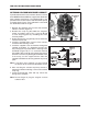
1. Remove the two Allen head screws that hold the
advance canister (Figure 9).
2. Remove the s nap ring that holds the m agn eti c
pickup assembly in place. This is easy to do with
a set of snap ring pliers by straddling one of the
reluctor paddles.
3. Gently lift up on the mag pickup plate and slide the
vacuum canister out.
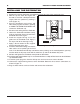
4. Install the Lockout Plate in place of the canister.
Install the two retaining screws.
5. Install the supplied screw and washer through the
Lockout and tighten. It is important to make sure
the pickup plate is parallel with the housing of the
distributor (Figure 10). If it is cocked or slanted,
the paddles of the reluctor may contact the pickup.
Check the clearance by rotating the distributor shaft.
If necessary, use the supplied shim s under the
Lockout hold-down to correctly position the pickup
plate.
Note: If no shims were require d, use one beneath
the washer of the Lock-Out Hold Down Screw.
6. After che cking the reluctor to pickup clea rance,
tighten the Lockout retaining screws and install the
snap ring.
7. I nstall the distr ibutor, rotor and cap. Check the
timing when complete.
Note: Do not forget to plug the original vacuum
advance hose.
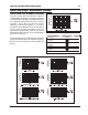
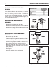
Figure 10 Checking Installation of the Lockout Plate.
Figure 9 Removing the Vacuum Canister.
RELUCTOR
PADDLES
CANISTER
SCREWS
MAG PICK-UP
PLATE
SNAP
RING