
Installation Manual

2 INSTALLATION INSTRUCTIONS
M S D • W W W . M S D P E R F O R M A N C E . C O M • ( 9 1 5 ) 8 5 7 - 5 2 0 0 • F A X ( 9 1 5 ) 8 5 7 - 3 3 4 4
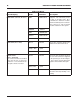
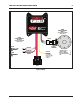
MSD 7730 Wiring
Wire
Lead Grouping Color Function Description
6-PIN CONN (TO Hub / Modules) RED MSD CAN HI Supplies 12V switched power
to add on module units. Also
communicates between modules
and Power Grid System Controller.
This connector is only used with
modules added onto the system.
BROWN SHIELD
RED POWER OUT
BLACK MSD CAN LO
BLACK MSD CAN GND
3-PIN CONN (DS to MSD) Green Ground These wires send the signal to the
MSD from the driveshaft sensor.
.
Purple / Blue Signal
Red Power
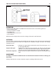
LOOSE WIRES Brown Ground These two wires should be inserted
into one of the connectors supplied
in the parts bag as shown in Figure
1. These wires send the driveshaft
signal from the MSD to Racepak.
White / Blue Signal
Yellow Active Indicator Provides ground to a circuit any time
the unit is active by retarding or rev
limiting.
(MSD to RACEPAK)
The connector must be assembled
using the two pin or three pin
connector to accommodate the
Racepak connector needed.