
Installation Owner's manual


2 INSTALLATION INSTRUCTIONS
M S D I G N I T I O N • W W W .M S D I GN IT I ON .C O M • (9 15 ) 8 5 7 -5 2 0 0 • F AX ( 9 15 ) 8 5 7 -3 3 4 4
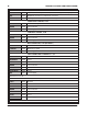
LOOSE WIRES
BLACK/GRAY Pin-A/B Ground. Connect to a ground source, such as the engine or battery negative.
PINK Pin-C On/Off wire. Connect to a switched 12 volt source.
YELLOW Tach Signal. Provides a 12 volt square wave signal.
CRANKSHAFT SENSOR, 3-PIN
ORANGE/YELLOW
Pin-A Crank Sensor Signal
BROWN Pin-B Sensor Ground
ORANGE Pin-C 5 Volt Supply
CAMSHAFT SENSOR, 3-PIN
BROWN/WHITE Pin-C Cam Sensor Signal
BROWN Pin-B Sensor Ground
ORANGE Pin-A 5 Volt Supply
MAP CONNECTOR, 3-PIN (OPTIONAL)
BROWN Pin-A Sensor Ground
LT. GREEN Pin-B MAP Sensor Signal
ORANGE Pin-C 5 Volt Supply
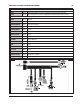
COIL CONNECTOR, CYLINDERS 2, 4, 6, 8
BLACK Pin-A Ground
RED/GREEN Pin-B Coil-2
BROWN/GREEN
Pin-C Coil-4
BROWN Pin-E Sensor Ground
WHITE/BLUE Pin-F Coil-6
VIOLET/BLUE Pin-G Coil-8
PINK Pin-H 12 Volt Supply
Note: Pin-D is not used.
COIL CONNECTOR, CYLINDERS 1, 3, 5, 7
BLACK Pin-A Ground
RED Pin-B Coil-7
GREEN Pin-C Coil-5
BROWN Pin-E Sensor Ground
LT. BLUE Pin-F Coil-3
VIOLET Pin-G Coil-1
PINK Pin-H 12 Volt Supply
Note: Pin-D is not used.