
User Manual


2 INSTALLATION INSTRUCTIONS
MSD IGNITION • 1490 HENRY BRENNAN DR., EL PASO, TEXAS 79936 • (915) 857-5200 • FAX (915) 857-3344
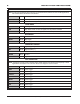
POWER WIRES
RED 12-volt input. Connect to switched 12 volts.
BROWN/YELLOW Use only with EFI. Coil input wire.
BLACK Ground. Connect eyelet to ground.
LOOSE WIRES
YELLOW Tach Signal. Provides a 12 volt square wave source.
PINK Step Retard. When 12 volts are applied, the step retard is activated.
BLUE 2-Step. When 12 volts are applied, the RevLaunch rpm value is active.
MAP SENSOR
BROWN
Pin-A Ground
GREEN Pin-B Map Signal
ORANGE Pin-C 5-volt supply
CRANKSHAFT SENSOR
BLACK Pin-A Signal Negative (-)
RED Pin-B Signal Positive (+)
CAMSHAFT SENSOR
BROWN Pin-A Ground
TAN Pin-B Signal Wire
COIL CONNECTORS
RED Pin-A* 12-volt supply
VIOLET
Pin-B* Coil-1 Trigger
RED/GREEN Pin-B* Coil-2 Trigger
LT. BLUE Pin-B* Coil-3 Trigger
BROWN/GREEN Pin-B* Coil-4 Trigger
GREEN Pin-B* Coil-5 Trigger
WHITE/BLUE Pin-B* Coil-6 Trigger
PINK Pin-B* Coil-7 Trigger
VIOLET/BLUE Pin-B* Coil-8 Trigger
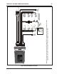
Note: For carburetor applications this connector is cut off and the Brown/Yellow is not used. For EFI applications,
this connects to the number one coil connector.
*Note: The harness is set up for use on a SOHC engine. DOHC engines use coils with reversed polarity. In these
applications, the location of two coil wires needs to be swapped in each connector.