
Installation Instruction Manual

INSTALLATION INSTRUCTIONS 3
M S D • W W W . M S D P E R F O R M A N C E . C O M • ( 9 1 5 ) 8 5 7 - 5 2 0 0 • F A X ( 9 1 5 ) 8 5 7 - 3 3 4 4
INSTALLATION INFO
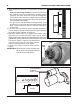
INSPECT PINION GEAR
After cranking the engine several times, you can inspect
the witness pattern on the pinion gear. The pattern should
show 1/4" to 3/8". If over, the internal shim is required.
SLOW CRANKING
The most common cause is due to low input voltage. The
battery should be checked, but also inspect the battery
wires, terminals, connections or switches.
DISCONNECT SWITCHES
Most sanctioning bodies require an emergency disconnect
switch. Be sure to use a heavy duty switch that is capable
of handling high current. Some starters may pull over 700
amps while cranking. Most disconnect switches are rated
at continuous and intermittent amps. Make sure to use a
switch that exceeds your starting and electrical system
requirements.
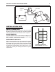
Figure 5 Wiring to Incorporate an External Solenoid.
BATTERY
+
-
FACTORY REMOTE SOLENOID
10-12 GAUGETO IGNITION
SWITCH
Figure 6 Pinion Gear Pattern.
THE CORRECT PINION DEPTH
SHOULD MEASURE 1/4” to 3/8”.