
Installation
18 INSTALLATION INSTRUCTIONS
MSD • WWW.ATOMICEFI.COM • (915) 855-7123 • FAX (915) 857-3344
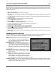
CLEAR FLOOD
If a flood condition occurs, turn the key on then press the accelerator to wide-open throttle. This tells
the ECU to turn off the injectors. Crank the engine to clear the flood condition until the engine starts
(release the throttle open start-up).
Note: The TPS is self calibrating so the key must be in the On position prior to pressing the accelerator.
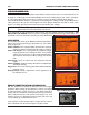
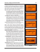
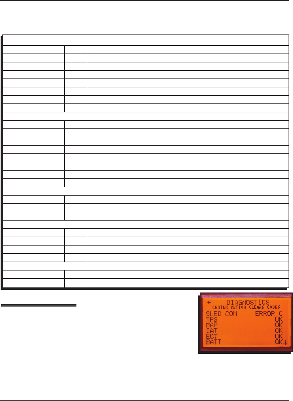
DIAGNOSTICS
There is a self-diagnosing system built into the Atomic EFI. Each
covered parameter can show a status in one of three ways.
“OK”: the parameter is functioning normally.
“Error C”: there is currently an error occurring.
“Error H”: there was previously an error that has been remediated
within the last ten ignition cycles.
Figure 23
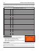
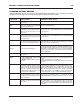
COIL CONNECTOR, CYLINDERS 2, 4, 6, 8
BLACK Pin-A Ground
TAN Pin-B Coil-2
LIGHT GREEN Pin-C Coil-4
BROWN Pin-E Sensor Ground
WHITE Pin-F Coil-6
LIGHT BLUE Pin-G Coil-8
PINK Pin-H 12 Volts Supply
Pin-D NOT USED
COIL CONNECTORS, CYLINDERS 1, 3, 5, 7
BLACK Pin-A Ground
BLUE Pin-B Coil-7
BROWN WHITE Pin-C Coil-5
BROWN Pin-E Sensor Ground
GREEN Pin-F Coil-3
TAN Pin-G Coil-1
PINK Pin-H 12 Volts Supply
Pin-D NOT USED
THROTTLE POSITION SENSOR (TPS)
ORANGE PIN-1 5V Reference
BLACK PIN-2 Ground
BLUE PIN-3 Signal out
IDLE AIR CONTROL (IAC)
ORANGE Pin-A Coil 1B
GRAY Pin-B Coil 1A
BLUE Pin-C Coil 2A
BLACK Pin-D Coil 2B
INTAKE AIR TEMPERATURE (IAT)
BLACK Pin-A Ground
VIOLET Pin-B Signal
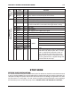
CONNECTOR AND WIRING INFORMATION
The following charts show the color, function and location on each connector in case you need to
remove or extend the wiring for relocated coils or a reversed intake manifold mount. More information
is available at www.atomicefi.com