
Owners manual

4 INSTALLATION INSTRUCTIONS
MSD • WWW.MSDPERFORMANCE.COM • (915) 857-5200 • FAX (915) 857-3344
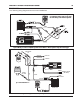
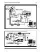
Figure 6 Wiring to Magnetic Pickup Trigger with an MSD 6 Series.
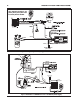
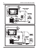
Figure 7 Installation to a GM HEI with a 5 or 7-Pin Module (Points Trigger).
WHITE
ORANGE
BLACK
MAGNETIC PICKUP
(NOT USED)
GRAY
TACH OUTPUT
GREEN (-)
VIOLET (+)
RED
DIGITAL 6A
The PN 8680 can be installed with
other magnetic distributors. The
polarity of the pick-up wires must
be correctly wired to the MSD.
MAGNETIC PICKUP
(NOT USED)
GREEN (-)
VIOLET (+)
GRAY
TACH OUTPUT
DIGITAL 6A
YELLOW
C-
GND
B+
18” BLACK TO
ENGINE GROUND
BLACK
TO GROUND
TIMING
CONTROL UNIT
A
D
V
A
N
C
E
TM
TIMING
CONTROL
MAGNETIC PICKUP
(NOT USED)