
Owners manual

INSTALLATION INSTRUCTIONS 3
M S D • W W W . M S D P E R F O R M A N C E . C O M • ( 9 1 5 ) 8 5 7 - 5 2 0 0 • F A X ( 9 1 5 ) 8 5 7 - 3 3 4 4
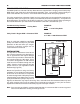
Once the charge wire gauge is selected (see
Figure 1), route the wire from the battery positive
terminal to the alternator charge stud. Make sure
to route the wire away from moving components
and high heat sources. Install ring lug terminals to
the ends of the wire and connect it to the battery
positive terminal and the charge post.
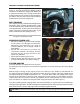
BELT TENSION
Once aligned properly, install the belt and tighten the
alternator in place. To check the belt tension, install
a 15/16" socket and 3/8” rachet wrench to the pulley
nut of the alternator. Try to turn the nut clockwise as
shown in Figure 3. The pulley should not turn, or just
barely move with the other pulleys turning.
Note: Pulley discolorization or excessive belt dust
are signs of improper tension.
PRE-START CHECK LIST
• Be sure the battery is good and fully charged.
A low battery can damage the alternator.
Remember that alternators are made to
maintain batteries, not to charge a weak or
dead battery.
• Review the instructions and check the
connection between the battery positive
terminal and the charge terminal of the
DynaForce Alternator.
• Reconnect the battery ground wire.
• Start the engine. Rev the engine to over 1,200
to excite the alternator so it starts charging.
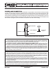
SYSTEM CHECKS
Once the alternator is installed and running, there
Figure 3 Checking Belt Tension.
Figure 4 Installing the Charge Wire.
are a few tests you can perform to ensure correct operation. For these checks you will need a digital
volt meter.
With the engine running, rev the engine once to over 1,200 rpm. This ‘wakes up’ the alternator for
it to begin charging as needed. Use a digital volt meter set to DC voltage, check the voltage across
the battery terminals. Voltage should be from 13 – 14.5 volts. Next, check the voltage at the output
terminal of the alternator to engine ground. Compare this value to that from the battery terminals.
There should not be more than a .40 volt drop between the two measurements. If there is, check for
poor connections or replace the charge wire with a larger diameter wire (See Figure 1).
If you are not seeing proper charging values, it is recommended to run a ground wire from the alternator
housing to the engine block. Powder coated and anodized brackets do not provide a good ground path.
Also confirm there’s a proper engine ground to the battery negative terminal.
CAUTION: Never disconnect the battery when the engine is running. Damage to the alternator will occur.