2.4~2.
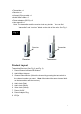
• Transmitter x 1 • Receiver x 1 • Infrared (IR) eye cable x 1 • Audio/Video cable x 2 • Power adaptors (DC6V) x 2 • User manual x 1 Note: The transmitter and the receiver look very similar. You can find “transmitter” and “receiver” labels on the side of the units. See Fig. 1. Fig. 1 Receiver Receiver Transmitter Transmitter Product Layout Transmitter/Receiver (See Fig. 2 and Fig. 3) 1. Power/Channel Indicator/IR Window 2. Audio/Video Antenna 3.
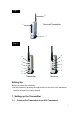
Fig. 2 2 Receiver/Transmitter 1 3 Fig. 3 4 4 5 5 6 6 7 7 8 8 9 Transmitter Receiver Setting Up Before you make the connection: • Set the channel by pressing the select button on the front of the transmitter and the receiver to the same channel. 1. Setting up the Transmitter 1.
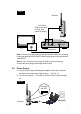
A/V Connection Connect the mini-plug of the provided A/V cables to the A/V jack on the rear of the transmitter; connect the other end of the cables to the A/V jacks (or Scart connector) of the A/V component labeled LINE OUT. See Fig. 4. Fig.
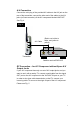
Fig. 5 Transmitter A/V Cable (Red to red, white to white, and yellow to yellow) RF OUT VHF/UHF VIDEO TV AUDIO IN A/V Component Note 1: On a NTSC system, the connector on the A/V equipment is an RCA jack. Connect the yellow plug to the jack labeled VIDEO, the red plug to the jack labeled AUDIO RIGHT and the white plug to the jack labeled AUDIO LEFT. Note 2: On a PAL system, connect the Scart connector labeled TRANSMITTER to the Scart connector labeled OUT on the A/V equipment.
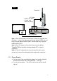
Fig. 6 POW ER ON-OFF Wall Outlet Transmitter 2. Setting up the Receiver 2.1 Connect the Receiver to a TV A/V Connect – for TV with A/V Input Jacks Connect the mini-plug of the provided A/V cables to the A/V jack on the rear of the receiver; connect the other end of the cable to the A/V jacks (or Scart connector) on the TV labeled LINE IN. See Fig. 7. Fig.
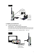
RF Connection – for TV without A/V Input Jacks If there is no A/V input jacks on your TV, you will need to get an RF modulator (available at your local electronics store) to make the connection between TV and receiver. See Fig. 8. Fig. 8 Receiver A/V Cable (Red to red, white to white, and yellow to yellow) VHF/UHF VIDEO TV AUDIO IN CH 3/4 RF OUT RF Modulator Connection through an A/V Component If an A/V component (VCR, DVD player, DBS receiver, and etc.
Fig. 9 Receiver A/V Cable (Red to red, white to white, and yellow to yellow) RF OUT VHF/UHF VIDEO TV AUDIO IN A/V Component Note 1: Connect the yellow plug to the jack labeled VIDEO, the red plug to the jack labeled AUDIO RIGHT and the white plug to the jack labeled AUDIO LEFT. Note 2: If the TV has only one input for audio (mono sound only), connect the white plug to that single audio in jack. 2.2 Power Supply a.
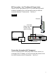
Other Applications Using Remote Control The Wireless A/V Sender gives you the ability to control A/V components from another room using your existing remote control device. To use this function, follow the steps below: 1. Place the transmitter next/close to the A/V source component and plug the IR eye into the jack located on the rear of the transmitter (IR Eye plug). Adhere the IR eye directly to the IR window on the front of the source component (see Fig.
2. Position the receiver so that your remote control signal can strike the IR window on the front of the receiver. Set the remote antenna on the receiver straight. Do not bend the remote antenna. 3. To use your remote control, point it at the front of the receiver and operate it as you normally would. Specifications Transmitter/Receiver A/V Transmitting Frequency IR Extender Frequency 2.4~2.5GHz (4 channel+4 Channel) 433.
modulator (3 or 4). If the signal is poor, or there is interference • Adjust the transmitter by rotating orientations until you get the best reception. • Change the channel on both transmitter and receiver and make them the same. • If there is a microwave oven in use in the path between the transmitter and receiver, remove the microwave oven or turn it off. • Make sure the transmitter and receiver are within range of each other (range of approximately 300 feet; 100 meters in a clear line of sight).
caused by unauthorized modifications to this equipment. could void the user's authority to operate the equipment.