
Specifications

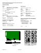


HDC-1801 HD Downconverter & DA with Analog Monitoring Output
Guide to Installation and Operation
HDC-1801 Page 3 of 17
UNPACKING
Make sure the following items have been shipped
with your HDC-1801. If any of the following items are
missing, contact your distributor or Miranda
Technologies Inc.
* HDC-1801 HD Downconverter & DA w/ audio mon.
* HDC-1801-DRP or HDC-1801-A-DRP rear panel
INSTALLATION
The HDC-1801 must be mounted in a DENSITÉ
frame. The installation includes both the HDC-1801
module, and the rear panel module. It is not
necessary to switch off the frame’s power when
installing or removing the HDC-1801.
Detailed instructions for installing cards and their
associated rear panels in the Densité frame are given
in the Densité Frame manual.
Rear panel installation
Note that the HDC-1801 has ten input & output
connectors, and making these available at the rear of
the frame requires a double-width rear panel.
When a double–width rear panel is used, the module
must be installed in the right-most of the two slots
associated with the rear panel in order to mate with
the rear-panel connectors. If it is placed in the wrong
slot, the front panel LED will flash red. Move the card
to other slot for correct operation. No damage will
result to the card should this occur.
OPERATION
Overview
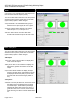
The HDC-1801 is equipped with an on-board LED
status indicator, mounted on the front edge of the
card so as to be visible from the front of the card
frame, even when the frame door is closed. The
functionality of this status monitor is described
below.The DENSITÉ frame incorporates a central
controller card, located in the center of the frame,
which is equipped with an LCD display. The card
handles error reporting and remote control for all
cards installed in the frame. The display shows the
error status of any card in the frame whose SELECT
button has been pushed.
The HDC-1801 is also equipped with the remote
reporting and control capabilities of the DENSITÉ
series. Fault reporting is carried out on a frame-wide
basis. There is no individual rear-panel access to the
fault and status reporting port of the HDC-1801.
Interfacing to the outside world is handled by the
frame’s controller card. The fault reporting protocol is
standardized across the DENSITÉ series of modules.
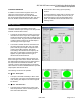
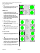
Status Monitor LED
The status monitor LED is located on the front card-
edge of the HDC-1801 module, and is visible through
the front access door of the DENSITÉ frame.
This multi-color LED indicates module status by
color, and by flashing/steady illumination, according
to the following chart. The chart also indicates fault
reporting for this card on the DENSITÉ frame’s serial
and GPI interfaces.
Status Indicator
REPORT COLOR (F=flashing)
SERIAL GPI G Y R FR
No errors
No input
signal or
input signal
error
DA only
mode
No audio
group 1
No audio
group 2
No audio
group 3
No audio
group 4
No CC
(HD/525) or
WSS (625)
No timecode
Test pattern
: Factory default.
NOTE: A “Flashing Yellow” Status LED indicates that
the SELECT button on the front panel has been
pushed, and the card is being accessed by the
controller. The LED color assignments for the various
error conditions can be reconfigured by the user.