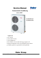
Service Manual Commercial Air Conditioning Home MRV AU482FIAIA AU48NFIAIA Features AC Inverter Auto-restart function Auto-changeover The Outdoor unit can match with max. 8 indoor unit Electronic expansion valve out to MP3(MP2),more silence Healthy negative ion generation function(optional) Haier Group MANUAL CODE: SYJS-019-03 rev.1 2003.
CONTENTS CONTENTS Contents……..............................................…...………...……........1 1. Description of Products & Features….......………………...…….3 2. Specifications…………………………. ………………..........……7 3. Safety precaution………………………….........…………………14 4. Net dimensions of indoor and outdoor unit…….......…………...16 5. Installation instructions ………………….......…. ………………..21 6. Parts and functions …………………......………..…… ..………..55 7. Remote controller functions………………………….……….......59 8.
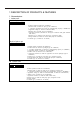
1 DESCRIPTION OF PRODUCTS & FEATURES 1.
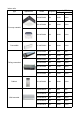
outdoor units appearance model AU482FIAIA refrigeran t R22 cooling heating connect capacity(HP) Min. Max. 48000 56000 2.5 capacity(BTU/h) Max. indoor units can be connected 6.5 8 AU48NFIAIA R22 48000 56000 2.5 6.
indoor units type appearance refrigerant capacity(BTU/h) cooling heating AB092FCAHA R22 10000 12000 AB142FCAHA R22 14000 17000 AB182FCAHA R22 18000 21000 AC182FCAHA R22 18000 21000 AE072FCAKA R22 7000 9000 AE242FCAKA R22 24000 28000 AE092FCAKA R22 9000 11000 AE122FCAKA R22 12000 14000 AE142FCAKA R22 14000 16000 AE182FCAKA R22 18000 21000 AE212FCAKA R22 21000 24000 AP182FAAHA R22 18000 21000 AS062FMAHA R22 6000 8000 AS072FMAHA R22 7000 9000 AS092FMA
4. Character of Products 1) 2) 3) 4) 5) 6) 7) 8) 9) 10) The length of horizontal refrigerant pipe can reach 70m,the total pipe length can reach 100m, the height difference between indoors unit and outdoor unit can reach 30m, the height difference between indoor units can reach 10m. 1000m super far distance communication between indoor and outdoor units, convenient control and easy to enlarge the scale of units assembly. Indoor unit can be controlled separately.
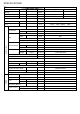
SPECIFICATIONS Item AU482FIAIA model Function Cooling Heating BTU/h 48000 56000 Total power input W 6000 6000 Max. power input W 7200 7000 Dehumidifying capacity 10‐³×m³/h / N,V,Hz 1N 220V 50HZ A/A cooling :32/38 heating :32/36 Capacity Power source Running current(max.
Item AU48NFIAIA model Function Cooling Heating BTU/h 48000 56000 Total power input W 6000 6000 Max. power input W 7200 7000 Capacity Dehumidifying capacity Power source Running current(max.
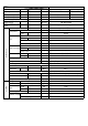
Item model AB092FCAHA AB142FCAHA Cooling capacity Heating capacity Cooling capacity Heating capacity Dehumidifying capacity Btu/h Btu/h W W 10‐³×m³/h 10000 12000 3200 4000 1.8 14000 17000 4000 5000 1.
Item Cooling capacity Heating capacity Cooling capacity Heating capacity Dehumidifying capacity model AE072FCAKA 7000 Btu/h 9000 Btu/h W 1800 W 2400 10‐³×m³/h 1.2 N,V,Hz 1PH 220V-230V 50HZ 1PH 220V-230V 50HZ Power source Refrigerant Noise level(H/M/L) R22 R22 dB(A) 36/-/centrifugal fan×2 36/-/centrifugal fan×2 m³/h 420 Relay control Combination of wave cranny radiation fin and copper pipe Capillary + Electronic expansion valve 663×440×225 11.6 6.35 9.
Item Cooling capacity Heating capacity Cooling capacity Heating capacity Dehumidifying capacity model AE212FCAKA 21000 Btu/h 24000 Btu/h W 6000 W 7000 10‐³×m³/h 2.
AS072FMAHA Btu/h 7000 Btu/h 9000 2500 W 3000 W 10‐³×m³/h 1.
Item AE142FCAKA model Cooling capacity Heating capacity Cooling capacity Heating capacity Dehumidifying capacity Btu/h Btu/h W W 10‐³×m³/h Power source N,V,Hz Refrigerant Noise level(H/M/L) 4000 5000 2 1PH 220V-230V 50HZ R22 dB(A) Type × Number Fan 14000 16000 Air-flow(H-M-L) m³/h 38/41/42 centrifugal fan×2 700 Relay control starting mothod Combination of wave cranny radiation Heat exchanger fin and copper pipe Capillary + Electronic expansion valve Refrigerant control method Dimension (L
SAFETY PRECAUTIONS 3 SAFETY PRECAUTIONS Please read these "Safety Precautions" first then accurately execute the installation work. Though the precautionary points indicated herein are divided under two headings, WARNING and CAUTION those points which are related to the strong possibility of an installation done in error resulting in death or serious injury are listed in the WARNING section.
SAFETY PRECAUTIONS WARNING When setting up or moving the location of the air conditioner, do not mix air etc. or anything other than the designated refrigerant (please see nameplate) within the refrigeration cycle. Rupture and injury caused by abnormal high pressure can result from such mixing. Always use accessory parts and authorized parts for installation construction. Using parts not authorized by this company can result in water leakage, electric shock, fire and refigerant leakage.
Net dimensions of indoor and outdoor A. model: AU48190 580 190 340 380 30 52 Screw Hole (M10) 88 960 25 1250 Power wiring Terminal Back Air-flow Hole L2 L3 L4 Installation Servicing Space(at Least) Unit:mm Back Airflow Hole L1 Outlet Air-flow Hole Repairing Space Installation Dimension Note : (1). Fix the parts with screws (2).Don't intake the strong wind directly to the outlet air-flow hole. (3).A one meter distance should be kept from the unit top (4).
Model: AB092FCAHA AB142FCAHA 2 40 30 75 362 18 122 5 104 35 660 48 660 270 170 32 131 113 90 70 30 270 45 92 Model: AB182FCAHA
Model: AC182FCAHA 0 0 2 9 Model: Wall mounted Aa Ac bA AS062FMAHA AS072FMAHA AS092FMAHA AS122FMAHA AS182FTAHA a 795 795 795 938 1100 b 182 182 182 182 205 c 265 265 265 265 330 240 5 5 6
Model: ceiling concealed 54 25 100 25 225 b a 0 R1 225 55 122 240 C 30 R5 OVER 250 93 a b c 615 702 452 AE122FCAKA 770 704 452 AE142FCAKA 770 704 452 AB182FCAKA 990 858 452 AE212FCAKA 990 858 452 unit model AE092FCAKA AE242FCAKA
Model: AP182FAAHA 250 500 1746 5
5 INSTALLATION STRUCTION 5.1 Piping dimensions charts model liquid pipe mm 9.52 6.35 6.35 9.52 9.52 6.35 6.35 6.35 6.35 9.52 9.52 9.52 9.52 6.35 6.35 6.35 6.35 9.52 AU48 AB09 AB14 AB18 AC18 AE07 AE09 AE12 AE14 AE18 AE21 AE24 AP18 AS06 AS07 AS09 AS12 AS18 gas pipe mm 19.05 12.7 12.7 15.88 15.88 9.52 9.52 12.7 12.7 15.88 15.88 15.88 15.88 9.52 9.52 12.7 12.7 15.
FQG-B180 gas pipe heat preservation material liquid pipe heat preservation material Refrigerant pipes between manifold pipes Total refrigerating amount of indoor unit Gas side Liquid side group after the manifold pipe Less than 38220Btu/h 15.9 9.52 38220~61157Btu/h 19.05 9.52 61157~126137Btu/h 25.4 12.7 Note: 1. Y-shape manifold pipe can be placed in horizontal or vertical direction 2. The manifold pipes must be welded with hard-solder 3.
In the file, the figure marked with "√" is permitted, and the figure marked with "×" is prohibited. You can confirm the position according to the actual condition. The refrigerant flow direction is always from the collective side to the divided side.
MP3、MP2 Electronic Expansion Valve Box figure: Connect with indoor liquid pipe 1 2 3 Cover Bottom 80mm Connect with outdoor liquid pipe Fetch out the power line and the connecting line. Pay attention to fix firmly with wiring clamp.
Outer diameter . 6.35mm Inner diameter 6.35mm Note: Cutoff the pipe of standard accessories according to indoor distribute pipe diameter, then connect it with MP3 For example: Outer diameter 6.35mm Inner diameter 9.52mm 9.52 Wax sealed Connect with pipe diameter 9.52mm on liquid side B、MP3(MP2) device installation position a、MP3(MP2) device should be counted on the vertical wall, maintenance cover panel must be to the outer, and open a maintenance door over 600mm out of the panel.
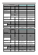
ADMISSIBLE COMBINATION EXAMPLES OF MULTIFLEX INVERTER Type of INDOOR UNITS CIRCUIT (×100W) 18 18 18 18 18 18 18 18 18 18 18 18 18 18 18 18 18 18 18 18 18 18 18 18 18 18 18 18 18 1.75 1.75 1.75 1.75 1.75 1.75 1.75 71 1.41 1.41 1.41 1.41 1.41 1.41 18 60 1.50 1.50 1.50 1.50 1.50 18 18 56 1.54 1.54 1.54 1.54 18 18 18 56 1.38 1.38 1.38 18 18 18 18 50 1.59 1.59 18 18 18 18 18 50 1.
ADMISSIBLE COMBINATION EXAMPLES OF MULTIFLEX INVERTER Type of INDOOR UNITS CIRCUIT REAL HEATING CAPACITY (OF EACH UNIT IN COMBINATION) kW REAL COOLING CAPACITY (OF EACH UNIT IN COMBINATION) Kw (×100W) kW TOTAL COOLING CAPACITY TOTAL HEATING CAPACITY 18 18 18 18 18 50 32 1.46 1.46 1.46 1.46 1.46 4.07 2.63 1.67 1.67 1.67 1.67 1.67 4.65 2.98 14.00 16.00 18 18 18 18 18 50 25 1.53 1.53 1.53 1.53 1.53 4.24 2.11 1.75 1.75 1.75 1.75 1.75 4.85 2.42 14.00 16.
ADMISSIBLE COMBINATION EXAMPLES OF MULTIFLEX INVERTER Type of INDOOR UNITS CIRCUIT REAL HEATING CAPACITY (OF EACH UNIT IN COMBINATION) kW REAL COOLING CAPACITY (OF EACH UNIT IN COMBINATION) Kw (×100W) kW TOTAL COOLING CAPACITY TOTAL HEATING CAPACITY 18 18 18 32 25 56 1.51 1.51 1.51 2.68 2.10 4.69 1.72 1.72 1.72 3.07 2.40 5.37 14.00 16.00 18 18 18 32 25 50 1.57 1.57 1.57 2.78 2.17 4.35 1.79 1.79 1.79 3.18 2.48 4.97 14.00 16.00 18 18 18 32 25 40 1.67 1.
ADMISSIBLE COMBINATION EXAMPLES OF MULTIFLEX INVERTER Type of INDOOR UNITS CIRCUIT REAL HEATING CAPACITY (OF EACH UNIT IN COMBINATION) kW REAL COOLING CAPACITY (OF EACH UNIT IN COMBINATION) Kw (×100W) kW TOTAL COOLING CAPACITY TOTAL HEATING CAPACITY 18 18 18 50 40 1.75 1.75 1.75 4.86 3.89 2.00 2.00 2.00 5.56 4.44 14.00 16.00 18 18 18 50 32 1.85 1.85 1.85 5.15 3.29 2.12 2.12 2.12 5.88 3.76 14.00 16.00 18 18 18 50 25 1.95 1.95 1.95 5.43 2.71 2.23 2.23 2.
ADMISSIBLE COMBINATION EXAMPLES OF MULTIFLEX INVERTER Type of INDOOR UNITS CIRCUIT REAL HEATING CAPACITY (OF EACH UNIT IN COMBINATION) kW REAL COOLING CAPACITY (OF EACH UNIT IN COMBINATION) Kw (×100W) kW TOTAL COOLING CAPACITY TOTAL HEATING CAPACITY 18 18 71 32 32 1.47 1.47 5.81 2.62 2.62 1.68 1.68 6.64 2.99 2.99 14.00 16.00 18 18 71 32 25 1.54 1.54 6.06 2.73 2.13 1.76 1.76 6.93 3.12 2.44 14.00 16.00 18 18 71 32 1.81 1.81 7.15 3.22 2.07 2.07 8.17 3.68 14.
ADMISSIBLE COMBINATION EXAMPLES OF MULTIFLEX INVERTER Type of INDOOR UNITS CIRCUIT REAL HEATING CAPACITY (OF EACH UNIT IN COMBINATION) kW REAL COOLING CAPACITY (OF EACH UNIT IN COMBINATION) Kw (×100W) kW TOTAL COOLING CAPACITY TOTAL HEATING CAPACITY 18 18 50 50 1.85 1.85 5.15 5.15 2.12 2.12 5.88 5.88 14.00 16.00 18 18 50 40 2.00 2.00 5.56 4.44 2.29 2.29 6.35 5.08 14.00 16.00 18 18 50 32 2.14 2.14 5.93 3.80 2.44 2.44 6.78 4.34 14.00 16.00 18 18 50 25 2.
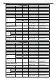
ADMISSIBLE COMBINATION EXAMPLES OF MULTIFLEX INVERTER Type of INDOOR UNITS CIRCUIT 18 18 18 18 18 25 25 25 25 25 25 25 25 25 25 25 25 25 25 25 25 25 25 25 25 25 25 25 25 25 25 25 18 18 18 18 18 25 25 25 25 25 25 25 25 25 25 25 25 25 25 25 25 25 25 25 25 25 25 25 25 25 25 25 18 18 18 18 18 25 25 25 25 25 25 25 25 25 25 25 25 25 25 25 25 25 25 25 25 25 25 25 25 25 25 25 18 18 32 25 18 25 25 25 25 25 25 25 25 25 25 25 25 25 25 25 25 25 25 25 25 25 71 71 71 71 71 60 25 18 25 25 25 25 25 25 25 25 25 40 40
ADMISSIBLE COMBINATION EXAMPLES OF MULTIFLEX INVERTER Type of INDOOR UNITS CIRCUIT 25 25 25 25 25 25 25 25 25 25 25 25 25 25 25 25 25 25 25 25 25 25 25 25 25 25 25 25 25 25 25 25 32 25 25 25 25 25 25 25 25 25 25 25 25 25 25 25 25 25 25 25 25 25 25 25 25 25 25 25 25 25 25 25 25 32 25 25 25 25 25 25 25 25 25 25 25 25 25 25 25 25 25 25 25 25 25 25 25 25 25 25 25 25 25 40 32 25 32 60 60 60 60 60 56 56 56 56 56 56 56 56 50 50 50 50 50 50 50 40 40 40 40 32 32 32 25 18 32 32 25 25 18 50 40 32 32 25 18 18 50
ADMISSIBLE COMBINATION EXAMPLES OF MULTIFLEX INVERTER Type of INDOOR UNITS CIRCUIT 32 32 32 32 32 32 32 32 32 32 32 32 32 32 32 40 40 40 40 40 40 40 40 40 40 40 40 40 40 40 40 40 50 32 32 32 32 32 32 32 32 32 32 32 32 32 32 32 40 40 40 40 40 40 40 40 40 40 40 40 40 56 50 40 32 50 32 32 32 32 32 32 32 32 32 32 50 40 32 25 18 40 40 40 40 40 40 40 56 50 40 32 25 18 50 32 32 32 32 32 50 40 32 25 18 40 56 50 40 32 25 18 25 50 40 32 25 18 18 REAL HEATING CAPACITY (OF EACH UNIT IN COMBINATION) kW REAL C
ADMISSIBLE COMBINATION EXAMPLES OF MULTIFLEX INVERTER Type of INDOOR UNITS CIRCUIT 50 50 50 50 50 50 50 50 50 50 50 50 50 50 56 56 56 56 56 56 56 56 56 56 56 56 56 56 60 60 60 60 60 50 50 50 50 50 50 50 50 60 56 50 40 32 25 56 56 56 56 56 56 71 60 56 50 40 32 25 18 60 60 60 60 60 50 60 56 50 40 32 25 18 56 50 40 32 25 18 60 56 50 40 32 18 REAL HEATING CAPACITY (OF EACH UNIT IN COMBINATION) kW REAL COOLING CAPACITY (OF EACH UNIT IN COMBINATION) Kw (×100W) 4.17 4.17 4.17 4.38 4.49 4.38 4.49 4.
ADMISSIBLE COMBINATION EXAMPLES OF MULTIFLEX INVERTER Type of INDOOR UNITS CIRCUIT 60 60 60 60 60 60 60 60 60 60 71 71 71 71 71 71 71 71 71 71 71 71 71 71 71 71 71 71 71 71 71 71 71 60 60 71 60 56 50 40 32 25 18 71 71 71 71 71 60 60 60 60 60 60 56 56 56 56 56 56 50 50 50 50 50 50 25 18 40 32 25 18 50 40 32 25 18 50 40 32 25 18 50 40 32 25 18 REAL HEATING CAPACITY (OF EACH UNIT IN COMBINATION) kW REAL COOLING CAPACITY (OF EACH UNIT IN COMBINATION) Kw (×100W) 5.79 6.09 5.79 6.09 6.41 2.41 1.83 6.
ADMISSIBLE COMBINATION EXAMPLES OF MULTIFLEX INVERTER Type of INDOOR UNITS CIRCUIT 71 71 71 71 71 71 71 71 71 71 71 71 71 71 71 40 40 40 40 40 32 32 32 32 25 25 25 18 18 40 32 25 18 32 25 18 25 18 18 REAL HEATING CAPACITY (OF EACH UNIT IN COMBINATION) kW REAL COOLING CAPACITY (OF EACH UNIT IN COMBINATION) Kw (×100W) 6.58 3.71 3.71 7.52 4.24 4.24 6.95 3.92 3.13 7.94 4.48 3.58 7.31 4.12 2.57 8.35 4.71 2.94 7.71 8.95 4.34 5.05 1.95 8.81 4.96 5.77 2.23 10.23 7.36 3.32 3.32 8.
8.3 Piping length and drop between units Haier MP2 H 1) When connected with 8 units,indoor units refer to 2) Total length=l1+l2*2+l3*4+l4*4+l5*4<=100m 3) Max. piping length =(l1+l2+l3+l5)<=70m 4) Max. piping length between the indoor unit and the first branch pipe<=30m 5) Max. drop between outdoor unit and indoor unit: H<=30m(indoor above outdoor);H<=20m(indoor below outdoor) 6) Max.
Combination example: 8 by 1: AS06 Haier AS06 electronic expansion valve AS06 AS06 AS06 AS06 AE07 MP2 AE07 NOTE: 1.When AU48 unit is connected with 8 indoor units, pay attention that the total capacity of indoor units must not exceed 130% of outdoor cooling capacity. 2.Wall-mounted type can be connected with 8 units by the outdoor unit. You can set the unit address with the new address setting controller (ASC-02). Its usage is in the following. 3.
8.4 Combination examples A. 6 by one AS09 (or other 9000BTU units) AS09 (or other 9000BTU units) Haier AS09 (or other 9000BTU units) AU48- AS09 (or other 9000BTU units) AS09 (or other 9000BTU units) Expansion valve AS09 (or other 9000BTU units) B.
C. 4 by one Haier AP18(or other 18000BTU,14000BTU units) AB09(or other 9000BTU,12000BTU units) AU48AS09(or other 9000BTU,12000BTU units) AC18(or other 18000BTU,14000BTU units) D.
8.
l l l l l l l l l l l work is not met with the requirements, overturn of the unit will occur resulting in accidents. The wiring work shall be done by a qualified person and referred to the “technical standard of electric equipment”, “indoor wiring regulation” and what the manual specified. Do use special circuit. If the capacity of the circuit is not enough or bad work, electric shock, fire and other accidents will happen.
8.8 Special Work and Main Points in Installation Warning l l During installation, if refrigerant l leakage occurs, take ventilation measurement immediately. l As soon as the leaked refrigerant gas meets fire, poisonous gas will generate. After finishing installation, confirm the refrigerant gas does not leak. If the refrigerant gas leaks in the room, once it meets heater, burner and gas stove etc. fire source, the poisonous gas will generate. A.
(4) Pipe connection of the outdoor unit Referring to the installation diagram in page 4, connect the indoor unit, outdoor unit, branch pipe and electronic expansion valve together by using the pipe connection method and welding method. (5) Test of airtight quality After connection of the refrigerant pipes, carry out airtight quality test.
8.9 Test of leakage after wiring work is finished After connection of the refrigerant pipes, carry out leakage test. In this test, pressurize to the pipes as shown in the below figure by using nitrogen tank. Close the valves of the gas side and liquid side totally. The nitrogen may enter the cycle system of the outdoor unit, so that, before pressurizing, the valve rods must be fastened. (Both the gas side and liquid side).
c. Vacuumize 2~3 hours according to the length of the pipe. When vacuuming, confirm the gas side and liquid side of the 2-way valve and 3-way valve shall be in full close state. d. When it is not lower than 200Pa after 2 hours or more vacuuming, vacuums for another 1 hour. If after more than 3 hours vacuuming it is still not lower than 200Pa, the leak part shall be found. e.
8.11 Refrigerant MRV central air conditioner uses refrigerant “R22”. This refrigerant itself is innocuous, non-combustible safety refrigerant. But then, when arranging the air conditioner equipment, it is necessary to take some steps to take precautions against in case of the indoors refrigerant leakage. Such as, the room size shall be taken into account to avoid making the concentration of the refrigerant not exceed the concentration limit and other relevant steps.
8.12 Electric wiring Note: l l l l l l l The air conditioner must use special circuit (over 40A), and wiring by the qualified electrician according to the wiring rules specified in national standard. The grounding wire and the neutral wire shall be strictly separated. Connect the neutral wire with grounding wire is incorrect. The electric leakage breaker must be installed. All the electric wire must be copper wire.
Wiring method 1. Wiring method of orbicular terminals For the connection wire with orbicular terminals, its wiring method is as shown in the right figure: remove the connecting screw, put the screw through the ring on the end of the wire, then connect to the terminal block and fasten screw. 2.
2. Do not connect the power line with different dimensions to the same grounding wire end. Improper contact will affect protection. 3. Keep a proper distance between the communication wire and the power line. Otherwise, abnormal communication will occur because of disturbance. 4. Do not connect the power line to the connecting end of communication wire. Incorrect connection will cause damage of connected unit. 5.The communication wire must be shielding wire.
a. Table of relation between dialing switch and outdoor unit number Digit 1 0 Bit 123 000 001 010 011 100 101 110 111 Digit 2 0 Digit 3 0 Unit number stood for 1 Preelected number Confirmed number after electrified 1 2 3 4 5 6 7 8 1 2 3 4 5 6 7 8 :0 :1 b. Setting of indoor unit number After installation or after adding new indoor units, when electrifying for the first time, it is necessary to set unit number to the indoor units (note: the cabinet type indoor unit has been set to be No.
After setting all the indoor units number, push the lock button of the outdoor dialing switch to locked position, unit number setting is unallowed. At this time, when indoor unit receives signals from special remote controller, it will give “Pi, Pi” sound twice to indicate refusing to change unit number. If finding the repeated set unit number in unit number setting, the buzzer will send “Pi, Pi” sound twice to refuse to set.
8.14 Checks after the installation After installation, please fill in the following form for easy daily maintenance: No. Model of indoor unit Factory No. of unit Site setting No. System belonged (A/B) 1 2 3 4 5 6 Check for installation and test run z z z z z z z z z z z Please operate the air conditioner according to the operation manual.
PARTS AND FUNCTIONS 6 PARTS AND FUNCTIONS Outdoor unit Air inlet Air outlet Compressor (Inside of unit) Cassette type Indoor unit Swing louver (Air flow direction can be adjusted by using the SWING button on the remote controller) Electrical Components Case Air Inlet Grille Air Filter (Inside of the Inlet Grille)
PARTS AND FUNCTIONS 6.Parts and functions Cassette type Indoor unit : Discharge unit (built in) In cooling operation,to discharge the water from inside the room.
PARTS AND FUNCTIONS Celing concealed type indoor unit - 49 -
Wall mounted type Indoor Unit AP182FAAHA 1 1. Outlet 2. Operation Board 2 3. Inlet 4. Inside 5. Dust Filter Inside 3 Operation Board 1. Health 2. Power 4 3. Time set 4. Running 5. On/off button Press this button to start the air conditioner for emergency operation. 6.
7 REMOTE CONTROLLER FUNCTIONS 7.1 Controllers 7.1.1 Wireless remote controller Signal Transmitter Mode Sending signals to the indoor unit receiver Operation option display Airflow volume AUTO Airflow volume display Speed is automatically adjusted by the air conditioner according to room and set temperatures.
7.1.3 Remote controller (new type) *** Remote controller 1.POWER ON/OFF used for unit start and stop Buttons and display of the remote controller 2.TEMPERATURE 20 11 12 15 AUTO 16 ion 13 17 18 OFF 14 3 . H E A LT H used to control the function of oxygenmaking and ion-adding (when oxygen device and ion-generator are both acquirable*health button can control them, whether oxygen device is acquirable lies on the function of its outdoor.) 4.
7.1.3 Wired remote controller (old type) Heating operation indication Dehumidifying operation indication Cooling operation indication Fan only operation indication Automatic operation Operation indicator Clock display Power ON/OFF key Used to turn on /off the machine.
7.1.4 Wired remote controller (new type) MODE CLOCK Used to select AUTO RUN, COOL, DRY, HEAT and FAN operation. Used to set correct time. TIMER Used to select TIMER ON, TIMER OFF, TIMER ON/OFF. Dial switch and Sensor FAN SPEED MODE FAN SWING Used to select fan speed: LO, MED, HI, AUTO AUTO TEMP SET % ON AM PM CLOCK SET TIMER SLEEP * ROOM Used to set clock and timer setting. Power ON/OFF Used for unit start and stop. Used to select your desired temp.
DRY HEAT FAN OPERATION COOL SLEEP AUTO MODE AUTO SET ON SWING TEMP % ROOM AM PM FAN • OFF AM PM CLOCK SET TIMER SLEEP FILTER RESET RESET ON/OFF FAN SPEED TIMER ON TIMER OFF CLOCK OPERATING LAMP Remote control TEMP. Clock set When unit is started for the first time, clock should be adjusted as follows: Press CLOCK button, "AM"or "PM" flashes. Press or to set correct time. Each press will increase or decrease 1min. If the button is kept depressed, time will change quickly.
Installation of receive display Because of the temperature sensitive device, do not install the receive display at straight sunlight place, either in front of air outlet grill, for it is effected greatly from cool air and heat air, the receive display is at least 20mm distance to the air outlet grill. Since there is light sensitive device which receives wireless remote signal, so do not installed behind the window curtain or other obstacles, in order not to obstruct the signal.
Installation of the wired remote controlller a. Remove upper part of wire Remove upper part of wire controller PCB is mounted on lower part of wire controller, be careful not to damage Upper part of wire controller Lower part of wire controller b. Install wire (1) For exposed installation, use 2 wood screws(accessory). (2) For recessed installation, use 2 wood screws(accessory). Note: Try as far as possible a flat surface for installation. Don't use excessive c.
8.
9 ELECTRICAL CONTROL FUNCTIONS 9.1 Function of special remote controller (Address setting) 1. Read function symbol Press “read” button , “1” flashes 1 time 2 2. Signal emitting symbol when “2” flashes ,it shows that remote controller is giving signal to indoor unit. press “8”button to select indoor unit number (1,2,3,4,5or6), then “3” flashes continuously ,press “7” to set indoor unit number 4.
9.1.1 Number setting dialing switch using method(wired remoted control type) The dialing switch is on indoor unit PCB. The indoor unit number setting method is as follows: OFF stand for NO.1 indoor unit Digit 1 0 1 0 1 0 1 Digit 2 0 0 1 1 0 0 Digit 3 0 0 0 0 1 1 stand for NO.2 indoor unit Digit 4 Not used Not used Not used Not used Not used Not used Unit number stand for 1 2 3 4 5 6 9.1.2 Indoor unit NO. lock switch (for model AU482FIAIA,AU48NFIAIA We have “indoor unit NO.
9.
(2) Turn on/off unit Control function treat module Off Power indicator turn off, operation indicator turn off On/off On Yes Trouble signal Trouble indication Off Mode determinatio Yes Abnormal operation n Buzzer sound twice, refuse to receive signal No Choose mode Cooling operation Heating operation Dehumidifying operation A Fan motor turn off, electronic expansion valve close, louver motor turn off
(3) Cooling operation Cooling operation No Swing flap in the cooling standard position Swing Yes Swing action Yes Automatic fan speed Adjust fan speed according to temperature set and in air temperature No Operate in speed set fan Electronic expansion valve: overheat control Swing flap: cooling standard position Fan motor: high speed Yes Test run No Yes Electronic expansion valve: overheat control. Swing flap: cooling standard position.
(4) Dehumidifying operation Dehumidifying operation No Swing flap in the cooling standard position Swing Yes Swing action Yes If enter cooling operation Adjust fan speed according to temperature set and in air temperature No No Determine if dehumidify according to in air temperature Yes Electronic expansion valves open, indoor unit fan motor weak wind Electronic expansion valves open, indoor unit fan motor weak wind Yes Electronic expansion valve totally open Antidefrosting No Send indoor Operat
(5) Heating operation Heating operation No Swing flap in set fan speed position Swing Yes Swing action Yes Defrosting On side: wind off, expansion valve steady Off side: Electronic expansion valve totally open No No Rated operation According to temperature sensor to adjust state and valve open degree Fan motor operate in rated fan speed Yes If stop unit protection Overload protection No Yes No (not rated operation) Electronic expansion valve close Auto fan speed Yes Operate in set fan spe
9.3 Defrost operation Flow Chart 1. The compressor operates heating over 25 minutes, after meeting the defrosting condition, it is permitted to enter defrosting. Defrosting process is unit-stop defrosting mode. Determining condition of defrosting is as follows: Unit-stop defrosting: (1) When outdoor ambient temperature is less than 2 , (outdoor ambient temperaturedefrosting sensor) is more than 9 , and keeping over 2 minutes, enter unit-stop defrosting.
2. Compressor control The compressor will start at 10Hz and running between 30Hz to 120Hz. In operation the compressor running frequency is determined by three elements : the number of indoor units in operation , the temperature difference of each indoor units between setting temperature and room temperature , the size of each indoor unit. 3.
10 DIAGNOSTIC INFORMATION (TROUBLE SHOOTING) 10.1 Fault Codes In order to make repair and maintenance convenient, we set “Automatic troubleshooting” function in indoor unit and centralized controller. If any abnormal phenomenon occurs in operation, you can determine the trouble part and condition from the display on the LED of outdoor PCB, or the trouble code on the wired controller.
10.2 AU48- diagnostic information and trouble shooting The failure code is displayed on the outdoor PCB; please diagnose the trouble according to the following code: Failure code Failure position Judgment measure 01 Outdoor defrosting sensor TE circuit 02 Ambient circuit temp. sensor TA Examine the sensor below 20H in cut circuit or over 1000H in short circuit for continuous 60 seconds, recoverable 03 Suction circuit temp.
minutes normally 14 Low pressure protection acts Cooling: examine Ps below 0.2kgG/cm2 for 30 (Ps) seconds continuously after compressor starts up; Heating: examine Ps below -0.2kgG/cm2 for 10 minutes continuously after compressor starts up; recoverable 15 High pressure protection acts (Pd) Examine sensor Pd over 27.5kgG/cm2 16 Suction temp. protection acts (TS) On compressor working, for continuous 10 minutes, examine sensor TS over 40℃, recover after 2 minutes.
10.3 Troubleshooting (1) Indoor unit trouble indication: timer indicator flashes (once, twice, 3 times, 7 times) Abnormal reasons: Heat sensitive resister is short circuit or open circuit The treatment to sensor output part in PC board is improper, such as poor contact of package part, the electrolytic capacitor for filtering is failed, etc. Treatment: Remove the heat sensitive resister, test and measure its numerical value.
Treatment: use the DC voltage grade of multimeter to test the plastic sealed motor to find if there is any feedback signal, determine if the plastic sealed motor is abnormal. If normal, change the indoor unit PC board. (6) Indoor unit trouble indication: Timer indicator flashes (12 times) Abnormal reason: Indoor unit PC board is improper Treatment: change the improper indoor unit PC board.
Refrigerant leaks Discharging air temperature heat sensitive resistor is improper Electronic expansion valve or 2-way valve is closed Treatment: check if there is leakage part, test system pressure in rated operation state to determine if there is leakage? Check the state of electronic expansion valve and 2-way valve. Test and measure the numerical value of discharging air temperature heat sensitive resister.
11.ELECTRICAL DATA 11.1 Wiring Diagram AU482FIAIA 11.1.
AU48NFIAIA white black red power module compressor filter capacitor condenser mid-part sensor SW06 LD1 LD2 LD3 suction sensor SW07 SW05 SW04 ambient temp.
4.1.
2) Model: AS182FTAHA 3) Model: AP182FAAHA Vapor pipe temperature sensor Control board Ambient temperature sensor Liquid pipe temperature sensor Terminal block Connect with outdoor unit Electronic expansion valve Negative ion generator Note: It is strictly prohibited to connect C1, C2 with 220V power Fan motor Fan motor capacitor Louver motor Color instruction: B : Black R: Red G: Green BL: Blue W: White Y/G: Yellow/Green OR: Orange Y: Yellow
4) Model: AB092FCAHA AB142FCAHA AB182FCAHA ELECTRO-EXPANSION VALVE M CN6 CN5 W serial 250VAC,3.15A GAS PIPING TEMP.SENSOR INDOOR PCB TEST CN16 CN17 CN18 B ROOM TEMP.SENSOR CN4 LIQUID PIPING TEMP.SENSOR FLOAT SWITCH BL B CN15 CN14 CN13 CN12 CN10 CN11 CN1 COM LO MED HI SIGNAL RECEIVER BOARD R R W B W B Y/G R Y Y Y/G R W M C1 C2 N L M M PUMP LOUVER MOTOR CAPACITOR FAN MOTOR TO OUTDOOR UNIT 5) Model: AC182FCAHA W GAS PIPING TEMP.SENSOR LIQUID PIPING TEMP.
MP3 wiring diagram: Electronic expansion valve wiring diagram FUSE T3.
AE072FCAKA、AE092FCAKA、AE122FCAKA、AE182FCAKA、AE212FCAKA、AE242FCAKA: Indoor unit wiring diagram M electronic expansion valve M refresh air fan motor blue 1 1 2 3 4 5 6 CN6 1 2 3 CN9 CN17 CN5 1 2 3 4 blue 2 3 CN8 black gas pipe temp. sensor liquid pipe temp. sensor NOTE:the dashed "---"in indoor controll board is PCB inner wiring. About control board outer connector: in the diagram,gas pipe temp. sensor 、liquid pipe temp.
4.2 Circuit Diagram 4.2.
Model: expansion valve MRV circuit diagram of control board for electrical expansion valve
Model: AS182FTAHA
Model: AB092FCAHA AB142FCAHA AB182FCAHA
Model: AC182FCAHA
AE072FCAKA\AE092FCAKA\AE122FCAKA\AE182FCAKA\AE212FCAKA\AE242FCAKA Circuit diagram 1 2 3 4 5 6 +5V +12V IC10 7805 D3 1N4007 1 28 2 27 C22 104 C21 100uF GND GND 10K L3 102 4.
MP3 circuit diagram:
Model: AP182FAAHA
12 EXPLODED VIEWS & PART LISTS 12.
Parts list No.
Parts list Spare parts No. number Spare parts description in English the proportion of the sparepart stock Remark Qty. Model Failure rate 1 2 3 4 5 001A0100122 001A1301707 001A1301640 001A5402022 001A3000201 Front guard assy Plate for maintain Front panel(left) Axial Fan Motor 2 1 1 2 2 AU48NFIAIA AU48NFIAIA AU48NFIAIA AU48NFIAIA AU48NFIAIA 0.00% 0.00% 0.00% 0.02% 0.02% 0.000% 0.000% 0.000% 0.024% 0.
AU482FIAIA / AU48NFIAIA
Parts list Spare parts No. number 1 2 3 4 5 6 7 8 9 10 11 12 13 14 0010150073 0010450036 0010450184 / 001A5745116 0010450037 0010450187 0010450188 0010450201 0010450200 / 0010450189 0010450190 001A3600018 0010150075 Spare parts description in English Electrical box PCB 1 power supply Terminal board / Terminal board PCB 2 rectifier rectifier power module dispel heat patch / electrolyse capacitance 1 electrolyse capacitance 2 Capacitor for fan motor Electrical box(level) Qty.
MODEL : AB092FCAHA AB142FCAHA
Parts list No.
Parts list No.
Parts list No.
Model: AC182FCAHA
Parts list No. Spare parts number Spare parts description in English Qty. Model Failure rate the proportion of the spare-part stock Remark 1 001A0100330 air inlet grill 1 AC182FCAHA 0.0000% 0.0000% × 2 001A2400087 air filter 2 AC182FCAHA 0.0000% 0.0000% × 3 001A1301395 teinforced rod 1 AC182FCAHA 0.0000% 0.0000% × 4 001A1431559 pinch plate 1 AC182FCAHA 0.0000% 0.0000% × 5 001A17001180 fixed board 1 AC182FCAHA 0.0000% 0.
Model: AE072FCAKA -AE242FCAKA,AE092-182FCAJA 20 21
Parts list No. Spare parts number Spare parts description in English Qty. Model Failure rate the proportion of the spare-part stock Remark 1 *0010850604.1 fan 2 AE072FCAKA 0.0200% 0.0240% * 2 *0010850604.2 scroll case 2 AE072FCAKA 0.0000% 0.0000% X 3 *0010850604.3 fan motor 1 AE072FCAKA 0.0200% 0.0240% * 4 0010400137 wire remote controller 1 AE072FCAKA 0.0100% 0.0120% 5 *0010850604.4 evaporator 1 AE072FCAKA 0.0000% 0.0000% X 6 *0010850604.
Parts list Spare parts number Spare parts description in English 1 0010250281 fan 2 AE092FCAKA 0.0200% 0.0240% * 2 0010850502 scroll case 2 AE092FCAKA 0.0000% 0.0000% X 3 0010450657 fan motor 1 AE092FCAKA 0.0200% 0.0240% * 4 0010400137 wire remote controller 1 AE092FCAKA 0.0100% 0.0120% 5 0010751752 evaporator 1 AE092FCAKA 0.0000% 0.0000% X 6 0010150328 shell 1 AE092FCAKA 0.0000% 0.
Spare parts No. number Parts list Spare parts description in English Qty. Model Failure rate the proportion of the spare-part Remark 1 0010250242 fan 2 AE142FCAKA 0.0200% 0.0240% * 2 0010850395 scroll case 2 AE142FCAKA 0.0000% 0.0000% X 3 0010450594 fan motor 1 AE142FCAKA 0.0200% 0.0240% * 4 0010400137 wire remote controller 1 AE142FCAKA 0.0100% 0.0120% 5 0010751728 evaporator 1 AE142FCAKA 0.0000% 0.0000% X 6 0010850387 shell 1 AE142FCAKA 0.0000% 0.
Parts list No. Spare parts number Spare parts description in English Qty. Model Failure rate the proportion of the sparepart stock Remark 0010250242 fan 2 AE212FCAKA 0.0200% 0.0240% * 2 0010850395 scroll case 2 AE212FCAKA 0.0000% 0.0000% X 3 0010450779 fan motor 1 AE212FCAKA 0.0200% 0.0240% * 4 0010400137 wire remote controller 1 AE212FCAKA 0.0100% 0.0120% 5 0010751748 evaporator 1 AE212FCAKA 0.0000% 0.0000% X 6 0010850387 shell 1 AE212FCAKA 0.0000% 0.
Parts list Spare parts No. number Spare parts description in English Qty. Model Failure rate the proportion of the spare-part stock Remark *0010850245.1 fan 2 AE092FCAJA 0.0200% 0.0240% * 2 *0010850245.2 scroll case 2 AE092FCAJA 0.0000% 0.0000% X 3 0010450543 fan motor 1 AE092FCAJA 0.0200% 0.0240% * 4 0010400137 wire remote controller 1 AE092FCAJA 0.0100% 0.0120% 5 *0010850245.3 evaporator 1 AE092FCAJA 0.0000% 0.0000% X 6 *0010850245.4 shell 1 AE092FCAJA 0.
MODEL : AP182FAAHA
AP182FAAHA No.
Model: AS062FMAHA AS072FMAHA AS092FMAHA AS122FMAHA 1 23 6 6 22 23 1 22 13 13 8 3 2 2 12 7 25 7 25 27 3 8 27 24 19 24 26 17 18 21 10 9 16 20 28 14 15 4 11 19 5 4
Parts list No. Spare parts number Spare parts description in English Qty. Model Failure rate the proportion of the spare-part stock Remark 1 001A1231076 Controller assy 1 AS062FMAHA 0.0100% 0.0120% 2 001A0600377 PCB(main conrtoller) 1 AS062FMAHA 0.0200% 0.0240% * 3 001A0600287 PCB(receiver) 1 AS062FMAHA 0.0000% 0.0000% X 4 001A1431366 motor cover 1 AS062FMAHA 0.0000% 0.0000% X 5 001A3900059 sensor (pipe temp) 1 AS062FMAHA 0.0100% 0.
Parts list No. Spare parts number Spare parts description in English Qty. Model Failure rate the proportion of the spare-part stock Remark 1 001A1231076 Controller assy 1 AS072FMAHA 0.0100% 0.0120% 2 001A0600377 PCB(main conrtoller) 1 AS072FMAHA 0.0200% 0.0240% * 3 001A0600287 PCB(receiver) 1 AS072FMAHA 0.0000% 0.0000% X 4 001A1431366 motor cover 1 AS072FMAHA 0.0000% 0.0000% X 5 001A3900059 sensor (pipe temp) 1 AS072FMAHA 0.0100% 0.
Parts list No. Spare parts number Spare parts description in English Qty. Model Failure rate the proportion of the spare-part stock Remark 1 001A1231081 Controller assy 1 AS092FMAHA 0.0100% 0.0120% 2 001A0600377 PCB(main conrtoller) 1 AS092FMAHA 0.0200% 0.0240% * 3 001A0600287 PCB(receiver) 1 AS092FMAHA 0.0000% 0.0000% X 4 001A1431371 motor cover 1 AS092FMAHA 0.0000% 0.0000% X 5 001A3900059 sensor (pipe temp) 1 AS092FMAHA 0.0100% 0.
Parts list No. Spare parts number Spare parts description in English Qty. Model Failure rate the proportion of the spare-part stock Remark 1 001A1431693 Controller assy 1 AS122FMAHA 0.0100% 0.0120% 2 0010400581 PCB(main conrtoller) 1 AS122FMAHA 0.0200% 0.0240% * 3 001A0600287 PCB(receiver) 1 AS122FMAHA 0.0000% 0.0000% X 4 001A1431494 motor cover 1 AS122FMAHA 0.0000% 0.0000% X 5 001A3900059 sensor (pipe temp) 1 AS122FMAHA 0.0100% 0.
1 2 3 4 32 33 34 31 30 29 5 28 35 6 27 36 7 37 38 26 8 25 39 9 40 10 42 41 43 24 23 22 21 11 12 13 14 20 19 18 17 16 15 Model: AS182FTAHA
Parts list No. Spare parts number Spare parts description in English Qty. Model Failure rate the proportion of the spare-part stock Remark 1 001A1231127 Front grille 1 AS182FTAHA 0.0000% 0.0000% X 2 001A1232119 Front panel 1 AS182FTAHA 0.0000% 0.0000% X 3 / / AS182FTAHA / / / / 4 001A2400076 Air filter 2 AS182FTAHA 0.0000% 0.0000% X 5 001A5002070 screw 2 AS182FTAHA 0.0000% 0.0000% X 6 001A0400065 Heat exchanger 1 AS182FTAHA 0.0100% 0.
AU48- Characteristics of refrigerating and heating capacity 1) Calculation method 1.1 1.1 1.0 1.0 0.9 0.9 -5 0.