
Install Manual
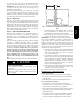
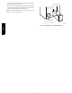
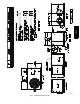
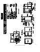
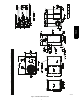
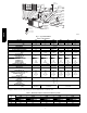
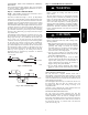
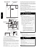
Table Of Contents

3
in. (1219 mm) above the unit top. The maximum horizontal
extension of a partial overhang must not exceed 48 in. (1219 mm).
IMPORTANT: Do not restrict outdoor airflow. An air restriction
at either the outdoor-- air inlet or the fan discharge may be
detrimental to compressor life.
Do not place the unit where water, ice, or snow from an overhang
or roof will damage or flood the unit. Do not install the unit on
carpeting or other combustible materials. Slab--mounted units
should be at least 4 in. (102 mm) above the highest expected water
and runoff levels. Do not use unit if it has been under water.
Step 4 — Place Unit
Unit can be moved with the rigging holds provided in the unit
base. Refer to Table 1 for operating weights. Use extreme caution
to prevent damage when moving the unit. Unit must remain in an
upright position during all moving operations. The unit must be
level with in 1/4 in. (6 mm) for proper condensate drainage; the
ground-- level pad must be level before setting the unit in place.
When a field --fabricated support is used, be sure that the support is
level and that it properly supports the unit.
Step 5 — Select and Install Ductwork
The design and installation of the duct system must be in
accordance with the standards of the NFPA for installation of
non--residence type air conditioning and ventilating systems,
NFPA 90A or residence type, NFPA 90B and/or local codes and
ordinances.
Select and size ductwork, supply--air registers, and return air grilles
according to ASHRAE (American Society of Heating,
Refrigeration, and Air Conditioning Engineers) recommendations.
Use the duct flanges provided on the supply-- and return--air
openings on the side of the unit. See Fig. 4 --6 for connection sizes
and locations. The 14-- in. (356 mm) round or 14 x 20 in. (356 x
508 mm) rectangular duct collars are shipped inside the unit
attached to the base pan in the indoor blower compartment.
They ar e field--installed and must be removed from the indoor
blower compartment prior to start--up, even if they are not
used for installation. If a corrugated shipping block is used
under the blower housing, remove and discard the block and
label.
When designing and installing ductwork, consider the following:
UNIT DAMAGE HAZARD
Failure to follow this caution may result in damage to unit
components.
When connecting ductwork to units, do not drill deeper
than 3/4 in. (19 mm) in shaded area shown in Fig. 2 or coil
may be damaged.
CAUTION
!
19.17 in.
(487 mm)
3.92 in.
(100 mm)
A10021
Fig. 2 -- Area Not to be Drilled More Than 3/4--in. (19 mm)
Deep
1. All units should have field --supplied filters or accessory
filter rack installed in the return--air side of the unit.
Recommended sizes for filters are shown in Table 1.
2. Avoid abrupt duct size increases and reductions. Abrupt
change in duct size adversely affects air performance.
IMPORTANT: Use flexible connectors between ductwork and
unit to prevent transmission of vibration. Use suitable gaskets to
ensure weather tight and airtight seal. When electric heat is
installed, use fireproof canvas (or similar heat resistant material)
connector between ductwork and unit discharge connection. If
flexible duct is used, insert a sheet metal sleeve inside duct. Heat
resistant duct connector (or sheet metal sleeve) must extend 24--in.
(610 mm) from electric heater element.
3. Size ductwork for cooling air quantity (cfm). The minimum
air quantity for proper electric heater operation is listed in
Table 2. Heater limit switches may trip at air quantities
below those recommended.
4. Seal, insulate, and weatherproof all external ductwork. Seal,
insulate and cover with a vapor barrier all ductwork passing
through conditioned spaces. Follow latest Sheet Metal and
Air Conditioning Contractors National Association
(SMACNA) and Air Conditioning Contractors Association
(ACCA) minimum installation standards for residential
heating and air conditioning systems.
5. Secure all ducts to building structure. Flash, weatherproof,
and vibration--isolate duct openings in wall or roof
according to good construction practices.
Fig. 7 shows a typical duct system with unit installed.
Installing factory--supplied duct flanges;
For 24, 30, and 36 sizes:
S Two round 14 --in. (356 mm) duct collars are factory supplied.
S Line up the 6 holes in the duct collar with the pre--drilled holes
in the side panel.
S Fasten duct collar to side panel using field--supplied screws.
For 42, 48 and 60 sizes (See Fig. 3):
S One round 14-- in. (356 mm) duct collar for the supply air
connections and two “L” brackets for the 14 --in. x 20 --in. (356 x
508 mm) return air connection are factory--supplied.
S Line up the 6 holes in the supply duct collar with the pre--drilled
holes in the side panel. Fasten duct collar to side panel using
field--supplied screws.
S For the return, remove the 4 screws on the left side of the return
and install one of the “L” flanges on the left side by replacing
the 4 screws. Using the 2 dimples below the return, align the
PH4Z