
Install Manual
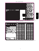

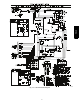
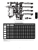
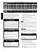
Table Of Contents

20
Electrical Controls and Wiring
Inspect and check the electrical controls and wiring annually. Be
sure to turn off the electrical power to the unit.
Remove access panel to locate all the electrical controls and wiring.
Check all electrical connections for tightness. Tighten all screw
connections. If any smoky or burned connections are noticed,
disassemble the connection, clean all the parts, re-- strip the wire
end and reassemble the connection properly and securely.
Check to ensure no wires are touching refrigerant tubing or sharp
sheet metal edges. Move and secure wires to isolate from tubing
and sheet metal edges.
After inspecting the electrical controls and wiring, replace all the
panels. Start the unit, and observe at least one complete cooling
cycle to ensure proper operation. If discrepancies are observed in
operating cycle, or if a suspected malfunction has occurred, check
each electrical component with the proper electrical
instrumentation. Refer to the unit wiring label when making these
checks. (See Fig. 14)
Refrigerant Circuit
Inspect all refrigerant tubing connections and the unit base for oil
accumulation annually. Detecting oil generally indicates a
refrigerant leak.
EXPLOSION, SAFETY AND ENVIRONMENTAL
HAZARD
Failure to follow this warning could result in personal
injury, death or equipment damage.
This system uses R-- 410A refrigerant which has higher
operating pressures than R--22 and other refrigerant. No
other refrigerant may be used in this system. Gauge set,
hoses, and recovery system must be designed to handle
R--410A. If you are unsure, consult the equipment
manufacturer.
!
WARNING
If oil is detected or if low cooling performance is suspected, leak
test all refrigerant tubing using an electronic leak detector, halide
torch or liquid--soap solution. If a refrigerant leak is detected, refer
to Check for Refrigerant Leaks section.
If no refrigerant leaks are found and low cooling performance is
suspected, refer to Checking and Adjusting Refrigerant Charge
section.
Indoor Airflow
The airflow does not require checking unless improper
performance is suspected. If a problem exists, be sure that all
supply-- and return--air grilles are open and free from obstructions,
and that the air filter is clean.
Metering Devices
Refrigerant cooling metering device is a piston located upstream of
the indoor coil distributor assembly. Refrigerant heating mode
metering device is a piston located upstream of the outdoor coil
distributor assembly.
High Flow Valves
High flow valves are located on the compressor hot gas and suction
tubes. Large black plastic caps distinguish these valves with
O--rings located inside the caps. Ensure the plastic caps are in place
and tight or the possibility of refrigerant leakage could occur . To
replace valve core body without removing charge, service tool p/n
SCFT20A is required.
High Pressure Switch
The high--pressure switch is located in the discharge line and
protects against excessive condenser coil pressure. It opens at 650
psig (4482 kPA). High pressure may be caused by a dirty
condenser coil, failed fan motor, or condenser air recirculation.
To check switch:
1. Turn off all power to unit.
2. Disconnect leads on switch.
3. Apply ohmmeter leads across switch. You should have
continuity on a good switch.
Loss of Charge Switch
The loss of charge switch is located in the liquid line and will
protect the compressor against a loss of charge condition. It opens
at 20 psig (138 kPa). If switch is open check system pressures. If
pressures are normal, check continuity and wiring of switch. Repair
or replace as required.
R--410A Compressor
The compressor used in this product is specifically designed to
operate with R-- 410A refrigerant and cannot be interchanged.
The compressor is an electrical (as well as mechanical) device.
Exercise extreme caution when working near compressors. Power
should be shut off, if possible, for most troubleshooting techniques.
Refrigerants present additional safety hazards.
EXPLOSION HAZARD
Failure to follow this warning could result in personal
injury or death and/or property damage.
Wear safety glasses and gloves when handling refrigerants.
Keep torches and other ignition sources away from
refrigerants and oils.
!
WARNING
Compressors vary in type by unit size. See Table 8 below for
compressor type by size.
Table 8 – Compressor Type
UNIT
COMPRESSOR
TYPE
MANUFACTURER SUGGESTED
OIL TYPE
024 Copeland Scroll 3MAF Polyolester Oil (POE)
030 Copeland Scroll 3MAF Polyolester Oil (POE)
036 LG Scroll RB32G Polyolester Oil (POE)
042 LG Scroll RB32G Polyolester Oil (POE)
048 LG Scroll RB32G Polyolester Oil (POE)
060 Copeland Scroll 3MAF Polyolester Oil (POE)
All compressors in these units have internal overload protection.
This protection will interrupt motor current under fault conditions
such as running current overload. The Copeland Scroll
compressors also have internal pressure relief that will relieve from
the high side to the low side if the differential is between 550 and
625 psig.
Refrigerant
EXPLOSION, ENVIRONMENTAL SAFETY
HAZARD
Failure to follow this warning could result in personal
injury, death or equipment damage.
This system uses R-- 410A refrigerant which has higher
operating pressures than R--22 and other refrigerants. No
other refrigerant may be used in this system. Gauge set,
hoses, and recovery system must be designed to handle
R--410A. If you are unsure, consult the equipment
manufacturer.
WARNING
!
PH4Z