
Install Manual
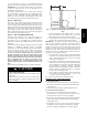
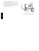
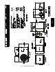
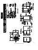
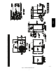
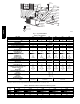
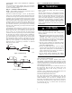
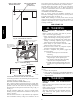
Table Of Contents

2
Metering Devices 20.................................
High Flow Valves 20.................................
High Pressure Switch 20..............................
Loss of Charge Switch 20.............................
R-- 410A Compressor 20...............................
Refrigerant 20......................................
Compressor Oil 21...................................
Servicing Systems on Roofs with Synthetic Materials 21......
Synthetic Roof Precautionary Procedure 21................
Liquid Line Filter Drier 21.............................
R-- 410A Refrigerant Charging 21.......................
TROUBLESHOOTING 21..............................
START-- UP CHECKLIST 21............................
SAFETY CONSIDERATIONS
Installation and servicing of this equipment can be hazardous due
to mechanical and electrical components. Only trained and
qualified personnel should install, repair, or service this equipment.
Untrained personnel can perform basic maintenance functions such
as cleaning and replacing air filters. All other operations must be
performed by trained service personnel. When working on this
equipment, observe precautions in the literature, on tags, and on
labels attached to or shipped with the unit and other safety
precautions that may apply.
Follow all safety codes. Wear safety glasses, protective clothing,
and work gloves. Use quenching cloth for brazing operations.
Have fire extinguisher available. Read these instructions
thoroughly and follow all warnings or cautions included in
literature and attached to the unit. Consult local building codes,
the current editions of the National Electrical Code (NEC) NFPA
70 and NFPA 90B--Installation Warm Air Heating and A/C
Systems (Residential). In Canada refer to the current editions of the
Canadian Electrical Code CSA C22.1.
Recognize safety information. This is the safety--alert symbol
.
When you see this symbol on the unit and in instructions or manu-
als, be alert to the potential for personal injury. Understand these
signal words: DANGER, WARNING, and CAUTION. These
words are used with the safety--alert symbol. DANGER identifies
the most serious hazards which will result in severe personal injury
or death. WARNING signifies hazards which could result in per-
sonal injury or death. CAUTION is used to identify unsafe practic-
es which may result in minor personal injury or product and prop-
erty damage. NOTE is used to highlight suggestions which will
result in enhanced installation, reliability, or operation.
ELECTRICAL SHOCK HAZARD
Failure to follow this warning could result in personal
injury or death.
Before installing or servicing system, always turn off main
power to system and install lockout tag. There may be
more than one disconnect switch. Turn off accessory heater
power switch if applicable.
!
WARNING
CUT HAZARD
Failure to follow this caution may result in personal injury.
Sheet metal parts may have sharp edges or burrs. Use care
and wear appropriate protective clothing, safety glasses and
gloves when handling parts and servicing.
!
CAUTION
PERSONAL INJURY AND ENVIRONMENTAL
HAZARD
Failure to relieve system pressure could result in personal
injury and/or death.
1. Relieve pressure and recover all refrigerant before
servicing existing equipment, and before final unit disposal.
Use all service ports and open all flow-- control devices,
including solenoid valves.
2. Federal regulations require that you do not vent
refrigerant into the atmosphere. Recover during system
repair or final unit disposal.
!
WARNING
INTRODUCTION
This packaged heat pump is fully self-- contained and designed for
outdoor installation (See Fig. 1). Standard units are shipped in a
horizontal-- discharge configuration for installation on a
ground-- level slab or directly on the ground if local codes permit.
Standard units can be converted to downflow (vertical) discharge
configurations for rooftop applications with a field supplied
plenum.
RECEIVING AND INSTALLATION
Step 1 — Check Equipment
IDENTIFY UNIT
The unit model number and serial number are printed on the unit
informative plate. Check this information against shipping papers.
INSPECT SHIPMENT
Inspect for shipping damage while unit is still on shipping pallet. If
unit appears to be damaged or is torn loose from its anchorage,
have it examined by transportation inspectors before removal.
Forward claim papers directly to transportation company.
Manufacturer is not responsible for any damage incurred in transit.
Check all items against shipping list. Immediately notify the
nearest equipment distribution office if any item is missing. To
prevent loss or damage, leave all parts in original packages until
installation.
Step 2 — Provide Unit Support
For hurricane tie downs, contact distributor for details and PE
(Professional Engineering) Certificate, if required.
SLAB MOUNT
Place the unit on a solid, level concrete pad that is a minimum of 4
in. (102 mm) thick with 2 in. (51 mm) above grade. The slab
should extend approximately 2 in. (51 mm) beyond the casing on
all 4 sides of the unit. Do not secure the unit to the slab except
when required by local codes.
A 6--in. (152 mm) wide gravel apron should be used around the
flat surface to prevent airflow blockage by grass or shrubs. The
unit should be level within 1/4 in. (6 mm). This is necessary for the
unit drain to function properly.
GROUND MOUNT
The unit may be installed either on a slab or placed directly on the
ground if local codes permit. Place the unit on level ground
prepared with gravel for condensate discharge.
Step 3 — Provide Clearances
The required minimum service clearances are shown in Fig. 4--6.
Adequate ventilation and outdoor air must be provided.
The outdoor fan draws air through the outdoor coil and discharges
it through the top fan grille. Be sure that the fan discharge does not
recirculate to the outdoor coil. Do not locate the unit in either a
corner or under an overhead obstruction. The minimum clearance
under a partial overhang (such as a normal house overhang) is 48
PH4Z