
Install Manual
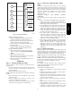
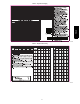

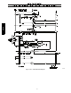
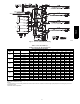
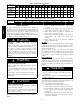
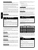
Table Of Contents

19
Indoor Blower and Motor
NOTE: All motors are pre--lubricated. Do not attempt to lubricate
these motors.
For longer life, operating economy, and continuing efficiency,
clean accumulated dirt and grease from the blower wheel and
motor annually.
ELECTRICAL SHOCK HAZARD
Failure to follow this warning could result in personal
injury or death.
Disconnect electrical power, and install lockout tag to the
unit before cleaning and lubricating the blower motor and
wheel.
!
WARNING
To clean the blower wheel:
1. Remove the blower housing:
a. Remove the screws on the external side of the duct
panel that fasten the housing to the duct panel assembly.
b. Remove the side access panel and unscrew the
mounting bracket that fastens the blower housing to the
internal partition panel of the control box assembly.
c. Make sure that the blower housing is supported by hand
before completely removing the mounting bracket.
d. Slide the blower housing from the rails of the duct panel
and place it outside the unit.
2. Remove the blower wheel fro m the housing:
a. Loosen the set screw which secures the wheel to the
motor shaft.
b. Loosen the three mounting legs of the motor by
removing the bolts that fasten the mounting legs to the
housing.
c. Slide out the motor assembly (motor, belly band and the
3 mounting legs) from the hub of the wheel.
d. Remove the filler panel at the discharge end of the
blower housing by removing the two screws that fasten
it to the housing.
e. Ensure proper reassembly by marking wheel orientation.
Remove the wheel from the housing.
3. Remove the caked on dirt from the wheel and the motor
using a brush.
4. Remove lint and dirt accumulations from the wheel and
housing with a vacuum cleaner, using a soft brush
attachment.
5. Remove grease and oil with a mild solvent.
6. Reassemble
a. Slip the wheel back in the housing with the hub set
screw parented in the correct direction.
b. Install the filler panel.
c. Reinsert the motor assembly in the wheel hub and align
the mounting legs with the housing mounting hold
locations.
d. Tighten the mounting bolts to fasten the motor assembly
with the housing.
e. Center the wheel in the housing by sliding it, align the
flat end of the shaft with the set screw and tighten the
set screw.
f. Slide back the blower housing into the mounting rails in
the duct panel and install the mounting bracket back in
its position.
g. Install the screws on the external side of the duct panel
to fasten duct panel with the housing.
h. Replace the side access panel.
Outdoor Coil, Indoor Coil, and Condensate Drain Pan
Inspect the condenser coil, evaporator coil, and condensate drain
pan at least once each year.
The coils are easily cleaned when dry; therefore, inspect and clean
the coils either before or after each cooling season. Remove all
obstructions, including weeds and shrubs, that interfere with the
airflow through the condenser coil.
Straighten bent fins with a fin comb. If coated with dirt or lint,
clean the coils with a vacuum cleaner , using the soft brush
attachment. Be careful not to bend the fins. If coated with oil or
grease, clean the coils with a mild detergent and water solution.
Rinse coils with clear water, using a garden hose. Be careful not to
splash water on motors, insulation, wiring, or air filter(s). For best
results, spray condenser coil fins from inside to outside the unit. On
units with an outer and inner condenser coil, be sure to clean
between the coils. Be sure to flush all dirt and debris from the unit
base.
Inspect the drain pan and condensate drain line when inspecting
the coils. Clean the drain pan and condensate drain by removing all
foreign matter from the pan. Flush the pan and drain trough with
clear water. Do not splash water on the insulation, motor, wiring, or
air filter(s). If the drain trough is restricted, clear it with a
“plumbers snake” or similar probe device.
Outdoor Fan Adjustment
UNIT OPERATION HAZARD
Failure to follow this caution may result in damage to unit
components.
Keep the condenser fan free from all obstructions to ensure
proper cooling operation. Never place articles on top of
unit.
CAUTION
!
1. Shut off unit power supply and install lockout tag.
2. Remove outdoor-- fan assembly (grille, motor, motor cover,
and fan) by removing screws and flipping assembly onto
unit top cover.
3. Inspect the fan blades for cracks or bends.
4. If fan needs to be removed, loosen the setscrew and slide the
fan off the motor shaft.
5. When replacing fan blade, position blade as shown in Fig.
16. Tighten setscrews.
A
FAN
HUB
MOTOR
SHAFT
HP UNIT
SIZE
024
030
036
042
048
A
in. (mm)
13/16 (20.6)
13/16 (20.6)
0
0
1/2 (12.7)
060
1/2 (12.7)
A150076
Fig. 16 -- Outdoor Fan Adjustment
PH4Z