
Install Manual
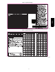

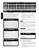
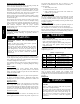
Table Of Contents

18
Table 6 – Filter Pressure Drop (IN. W.C.)
FILTER SIZE
in. (mm)
CFM
500 600 700 800 900 1000 1100 1200 1300 1400 1500 1600 1700 1800 1900 2000 2100 2200
20X20X1
(508X508X25)
0.05 0.07 0.08 0.10 0.12 0.13 0.14 0.15 — — — — — — — — — —
20X24X1
(508X610x25)
— — — 0.08 0.09 0.10 0.11 0.13 0.14 0.15 0.16 — — — — — — —
24X30X1
(610X762x25)
— — — 0.04 0.05 0.06 0.07 0.07 0.08 0.09 0.10 — — — — — — —
24X36X1
(610X914X25)
— — — — — — — 0.06 0.07 0.07 0.08 0.09 0.09 0.10 0.11 0.12 0.13 0.14
Table 7 – Accessory Electric Heat Pressure Dr op (IN. W.C.)
HEATER kW
CFM
800 1000 1200 1400 1600 1800 2000 2200
5--20 0.033 0.037 0.042 0.047 0.052 0.060 0.067 0.075
MAINTENANCE
To ensure continuing high performance, and to minimize the
possibility of premature equipment failure, periodic maintenance
must be performed on this equipment. This cooling unit should be
inspected at least once each year by a qualified service person. To
troubleshoot unit, refer to Table 9, Troubleshooting Chart.
NOTE TO EQUIPMENT OWNER: Consult your local dealer
about the availability of a maintenance contract.
PERSONAL INJURY AND UNIT DAMAGE
HAZARD
Failure to follow this warning could result in personal
injury or death and possible unit component damage.
The ability to properly perform maintenance on this
equipment requires certain expertise, mechanical skills,
tools and equipment. If you do not possess these, do not
attempt to perform any maintenance on this equipment,
other than those procedures recommended in the Owner’s
Manual.
!
WARNING
ELECTRICAL SHOCK HAZARD
Failure to follow this warning could result in personal
injury or death.
1. Turn off electrical power to the unit and install lockout
tag before performing any maintenance or service on this
unit.
2. Use extreme caution when removing panels and parts.
3. Never place anything combustible either on or in contact
with the unit.
!
WARNING
UNIT OPERATION HAZARD
Failure to follow this caution may result in equipment
damage or improper operation.
Errors made when reconnecting wires may cause improper
and dangerous operation. Label all wires prior to
disconnecting when servicing.
!
CAUTION
The minimum maintenance requirements for this equipment are as
follows:
1. Inspect air filter(s) each month. Clean or replace when
necessary.
2. Inspect indoor coil, drain pan, and condensate drain each
cooling season for cleanliness. Clean when necessary.
3. Inspect blower motor and wheel for cleanliness each
cooling season. Clean when necessary.
4. Check electrical connections for tightness and controls for
proper operation each cooling season. Service when
necessary.
5. Ensure electric wires are not in contact with refrigerant
tubing or sharp metal edges.
Air Filter
IMPORTANT: Never operate the unit without a suitable air filter
in the return--air duct system. Always replace the filter with the
same dimensional size and type as originally installed. See Table 1
for recommended filter sizes.
Inspect air filter(s) at least once each month and replace
(throwaway--type) or clean (cleanable--type) at least twice during
each cooling season and twice during the heating season if electric
heat is installed, or whenever the filter becomes clogged with dust
and lint.
Unit Top Removal
NOTE: When performing maintenance or service procedures that
require removal of the unit top, be sure to perform all of the routine
maintenance procedures that require top removal, including coil
inspection and cleaning, and condensate drain pan inspection and
cleaning.
ELECTRICAL SHOCK HAZARD
Failure to follow this warning could result in personal
injury or death.
Disconnect electrical power, and install lockout tag to the
unit before removing top.
!
WARNING
Only qualified service personnel should perform maintenance and
service procedures that require unit top removal.
Refer to the following top removal procedures:
1. Unplug all three wires from the outdoor fan motor.
2. Remove screws on unit top cover flange. (Save all screws.)
3. Lift top from unit carefully . Set top on edge and make sure
that top is supported by unit side that is opposite duct (or
plenum) side.
4. Carefully replace and secure unit top to unit, using screws
removed in Steps 1 and 2, when maintenance and/or service
procedures are completed.
PH4Z