
Install Manual
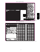

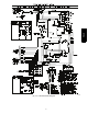
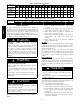
Table Of Contents

14
Step 4 — Indoor Airflow and Airflow Adjust-
ments
UNIT OPERATION HAZARD
Failure to follow this caution may result in equipment
damage or improper operation.
For cooling operation, the recommended airflow is 350 to
450 cfm for each 12,000 Btuh of rated cooling capacity .
!
WARNING
Table 5 shows wet coil air delivery for horizontal discharge units.
NOTE: Be sure that all supply-- and return-- air grilles are open,
free from obstructions, and adjusted properly.
ELECTRICAL SHOCK HAZARD
Failure to follow this warning could result in personal
injury or death.
Disconnect electrical power to the unit and install lockout
tag before changing blower speed.
!
WARNING
Blower speed tap can be changed by replacing the factory installed
blue low speed tap wire (cooling) with the unused black high speed
wire in unit control box. The red medium speed wire is factory
installed to operate with a call for supplemental electric heat. See
unit wiring diagram.
Be sure new airflow meets the range noted above and minimum
electric heat CFM, if equipped. Refer to Table 2 and 5.
All model sizes are factory wired or rated airflow operation.
Step 5 — Sequence of Operation
FAN OPERATION
The FAN switch on the thermostat controls indoor fan operation.
When the FAN switch is placed in the ON position, the indoor
(evaporator) fan motor (IFM) is energized through the G terminal
on the thermostat. The motor’s internal logic then provides power
to the indoor (evaporator) fan motor (IFM). The IFM will run
continuously when the FAN switch is set to ON.
When the FAN switch is set to AUTO, the thermostat deenergizes
the IFM (provided there is not a call for cooling). The contacts
open and the IFM is deenergized. The IFM will be energized only
when there is a call for cooling, in heat pump heating mode or if
the unit is equipped with accessory electric heat, the indoor--fan
motor will also run while the accessory electric heat is energized.
NOTE: Motors on this product are programmed for 60 second
time delay on tap 1 and 30 second time delay on tap 2. There is no
time delay on tap 3. The indoor fan will remain ON for the set time
delay after G or W2 is de--energized.
COOLING OPERATION
With a call for cooling (Y), the compressor, outdoor fan, and
indoor fan start immediately. When the cooling demand is met, Y
de--energizes, shutting the compressor, indoor fan and the outdoor
fan.
HEATING OPERATION
With a call for heating (Y), the compressor, outdoor fan, and
indoor fan start immediately. If Y cannot satisfy the heating
demand, the auxiliary or backup heat (W2) energizes. In case of
staged heating, W3 is ener gized if the demand is not met. When
heating demand is met, W3, W2 and Y sequentially de--energize
shutting the compressor, indoor fan and the outdoor fan.
CONTINUOUS FAN
With the continuous indoor fan option selected on the thermostat,
G is continuously energized. The continuous fan speed will be the
same as the cooling fan speed.
DEFROST
Defrost board (DB) is a time and temperature control, which
includes a field--selectable time period between checks for defrost
(30, 60, 90 and 120 minutes). The time period is factory --set at 60
minutes and should only be adjusted by a trained service person.
Electronic timer and defrost cycle start only when contactor is
energized and defrost thermostat (DFT) is closed.
Defrost mode is identical to Cooling mode. The outdoor fan motor
stops because of “OF1” and “OF2” contacts opening on the defrost
board, a bank of optional electric heat turns on to warm air
supplying the conditioned space.
ELECTRIC RESISTANCE HEATING
If accessory electric heaters are installed, on a call for “Emergency
Heat” the thermostat energizes W which energizes the heater relay
and in turn ener gizes the electric heaters. The IFM is energized
which starts the indoor--fan motor. If the heaters are staged, W2 is
energized when the second stage of heating is required. When the
need for heating is satisfied, the heater and IFM are de--energized.
PH4Z