
Install Manual
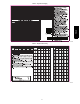

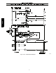
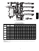
Table Of Contents

12
table do not attempt to charge unit under these conditions or
refrigerant slugging may occur. In this situation refrigerant
must be evacuated and weighed in. See rating plate for
charge quantity.
7. Refer to Required Suction Tube Temp. Table (Table 3).
Find superheat temperature located in Step 6 and suction
pressure. At this intersection note suction line temperature.
8. If unit has a higher suction line temperature than charted
temperature, add refrigerant until charted temperature is
reached.
9. If unit has a lower suction line temperature than charted
temperature, reclaim refrigerant until charted temperature is
reached.
10. If outdoor air temperature or pressure at suction port
changes, charge to new suction line temperature indicated
on chart.
048-- 060 Units, TXV
1. Measure Discharge line pressure by attaching a gauge to the
service port.
2. Measure the Liquid line temperature by attaching a tempera-
ture sensing device to it.
3. Insulate the temperature sensing device so that the Outdoor
Ambient doesn’t affect the reading.
4. Refer to the required Subcooling in Table 4 based on the
model size and the Outdoor Ambient temperature.
5. Interpolate if the Outdoor ambient temperature lies in be-
tween the table values.
6. Find the Pressure Value in the table corresponding to the
measured Pressure of the Compressor Discharge line.
7. Read across from the Pressure reading to obtain the Liquid
line temperature for a required Subcooling.
8. Add Charge if the measured temperature is higher than the
table value.
9. Remove charge if the measured temperature is lower than
the table value.
HEATING MODE CHARGE
Do not attempt to adjust charge by cooling methods while in heat
pump heating mode. Recover refrigerant and weigh in according to
unit data plate refrigerant data.
PH4Z