
Install Manual
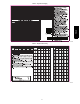

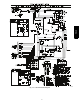
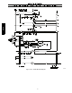
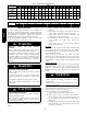
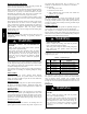
Table Of Contents

11
Thermostat
Unit Control
G
Y
W2
R
RED
GREEN
YELLOW
O
ORANGE
C
BROWN
WHITE
and subbase
Power
A10026
Fig. 13 -- Control Connections
3. Make the following inspections:
a. Inspect for shipping and handling damages, such as
broken lines, loose parts, disconnected wires, etc.
b. Inspect all field-- and factory--wiring connections. Be
sure that connections are completed and tight.
c. Ensure wires do not touch refrigerant tubing or sharp
sheet metal edges.
d. Inspect coil fins. If damaged during shipping and
handling, carefully straighten fins with a fin comb.
4. Verify the following conditions:
a. Make sure that outdoor--fan blade is correctly posi-
tioned in fan orifice. See Outdoor Fan Adjustment
section.
b. Make sure that air filter is in place.
c. Make sure that condensate drain pan and trap are filled
with water to ensure proper drainage.
d. Make sure that all tools and miscellaneous loose parts
have been removed.
START--UP
Step 1 — Check for Refrigerant Leaks
Proceed as follows to locate and repair a refrigerant leak and to
charge the unit:
1. Locate leak and make sure that refrigerant system pressure
has been relieved and reclaimed from both high -- and
low--pressure ports.
2. Repair leak following accepted practices.
NOTE: Install a filter drier whenever the system has been opened
for repair.
3. Add a small charge of R --410A refrigerant vapor to system
and leak--test unit.
4. Recover refrigerant from system and evacuate to 500
microns if no additional leaks are found.
5. Charge unit with R -- 410A refrigerant, using an accurate
scale. Refer to unit rating plate for required charge.
Step 2 — Start--Up Cooling and Make Adjust-
ments
Complete the required procedures given in the Pre--Start-- Up
section before starting the unit. Do not jumper any safety devices
when operating the unit. Do not operate the unit in cooling mode
when the outdoor temperature is below 40F(4.4C) (unless
accessory low--ambient kit is installed). Do not rapid cycle the
compressor. Allow 5 min. between “on” cycles to prevent
compressor damage.
CHECKING COOLING AND HEATING CONTROL
OPERATION
Start and check the unit for proper cooling control operation as
follows:
1. Place room thermostat SYSTEM switch in OFF position.
Observe that b lower motor starts when FAN switch is
placed in ON position and shuts down within 60 sec. when
FAN switch is placed in AUTO position.
2. Place SYSTEM switch in COOL position and FAN switch
in AUTO position. Set control below room temperature.
Observe that compressor, outdoor fan, and indoor blower
motors start and that reversing valve shifts. Observe that
cooling cycle shuts down when control setting is satisfied.
Reversing valve (RV) remains ener gized.
3. Place system switch in HEAT position. Observe that
compressor, indoor fan and outdoor fan energize (Reversing
Valve is deenergized in heat pump heating mode). Set
control above room temperature. Observe that heating cycle
shuts down when control setting is satisfied.
4. When using an automatic changeover room thermostat,
place both SYSTEM and FAN switches in AUTO positions.
Observe that unit operates in Cooling mode when
temperature control is set to call for Cooling (below room
temperature), and unit operates in Heating mode when
temperature control is set to call for Heating (above room
temperature).
Step 3 — Refrigerant Charge
Refrigerant Charge — The refrigerant system is fully charged with
R--410A refrigerant and is tested and factory sealed. Amount of
refrigerant char ge is listed on unit nameplate and in Table 1. Unit
must operate a minimum of 15 minutes before checking charge.
NOTE: Adjustment of the refrigerant charge is not required unless
the unit is suspected of not having the proper R--410A charge.
NOTE: Unit sizes 024--042 have fixed orifice refrigerant metering
devices. There is a different charging procedure for both expansion
devices. Refer to the correct procedure for your unit.
NO CHARGE
Use standard evacuating techniques. After evacuating system,
weigh in the specified amount of refrigerant (refer to Table 1).
LOW CHARGE COOLING
024-- 042 Units, Fixed Metering Device:
1. Operate unit a minimum of 10 minutes before checking
charge.
2. Measure suction pressure by attaching an accurate gauge to
compressor suction side service port.
3. Measure suction side temperature by attaching an accurate
thermisitor type or electronic thermometer to suction line
about 10 in. from compressor.
4. Measure outdoor air dry--bulb temperature with thermo-
meter.
5. Measure indoor air (return air) wet--bulb temperature with a
sling psychrometer or electronic equivalent.
6. Using Superheat Charging Table (Table 3) find outdoor
temperature and indoor air wet-- bulb temperature. At this
intersection note superheat. Where a dash (---- ) appears on
PH4Z