Metering Devices . . . . . . . . . . . . . . . . . . . . . . . . . . . . . . . . . High Flow Valves . . . . . . . . . . . . . . . . . . . . . . . . . . . . . . . . . High Pressure Switch . . . . . . . . . . . . . . . . . . . . . . . . . . . . . . Loss of Charge Switch . . . . . . . . . . . . . . . . . . . . . . . . . . . . . R--410A Compressor . . . . . . . . . . . . . . . . . . . . . . . . . . . . . . . Refrigerant . . . . . . . . . . . . . . . . . . . . . . . . . . . . . . . . . . . . . . Compressor Oil .
in. (1219 mm) above the unit top. The maximum horizontal extension of a partial overhang must not exceed 48 in. (1219 mm). IMPORTANT: Do not restrict outdoor airflow. An air restriction at either the outdoor--air inlet or the fan discharge may be detrimental to compressor life. Do not place the unit where water, ice, or snow from an overhang or roof will damage or flood the unit. Do not install the unit on carpeting or other combustible materials. Slab--mounted units should be at least 4 in.
bottom of the “L” flange with the two dimples and attach using filed--supplied thread--cutting screws. For the second “L” flange, align flange with the three dimples to the right of the return and the two dimples above the return and attach using field--supplied thread--cutting screws. 3 Factory Installed Screws (Must not be removed) Remove 4 screws from left side of duct opening and reuse to install the left half of duct flange.
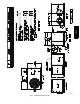
PH4Z A1456 Fig.
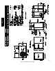
PH4Z A14557 Fig.
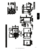
PH4Z A150072 Fig.
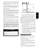
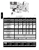
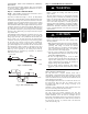
INDOOR THERMOSTAT RETURN AIR FROM POWER SOURCE TOP COVER POWER AND LOW-VOLTAGE ENTRY DISCONNECT PER NEC (UNIT AND ELECTRIC HEATER) COMPOSITE RUST-PROOF BASEPAN Power Wiring Control Wiring CONDENSATE DRAIN CONNECTION Condenser Airflow PH4Z Evaporator Airflow A08207 Fig. 7 -- Typical Installation Table 1 – Physical Data UNIT SIZE NOMINAL CAPACITY (ton) SHIPPING WEIGHT (lb) (kg) COMPRESSOR TYPE REFRIGERANT REFRIGERANT QUANTITIY (lb) QUANTITY (kg) OUTDOOR METERING DEVICE ORIFICE OD (in.
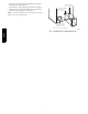
Step 7 — Install Electrical Connections ! ELECTRICAL SHOCK HAZARD Step 6 — Connect Condensate Drain Failure to follow this warning could result in personal injury or death. NOTE: When installing condensate drain connection be sure to comply with local codes and restrictions. Unit removes condensate through a 1--3/64 in. (27 mm) ID hole (using 3/4--in. (19 mm) ID piping or tubing) which is located at the end of the unit. See Fig. 4--6 for location of condensate connection.
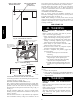
HIGH-VOLTAGE POWER WIRING ENTRY HOLE LOW-VOLTAGE WIRING ENTRY HOLE (grommet hole) brown leads in unit low voltage box, check fuse in red lead near transformer. Replace with Littelfuse brand, part number 257003. Unit main harness also contains a 1k ohm, 3 watt load resistor wired across low voltage leads “G” and “C”. Purpose of resistor is to provide a small electrical load for the indoor thermostat fan circuit to ensure reliable operation.
BROWN C RED R GREEN G YELLOW Y ORANGE O WHITE W2 Unit Control Power Thermostat and subbase A10026 Fig. 13 -- Control Connections 3. Make the following inspections: a. Inspect for shipping and handling damages, such as broken lines, loose parts, disconnected wires, etc. b. Inspect all field-- and factory--wiring connections. Be sure that connections are completed and tight. c. Ensure wires do not touch refrigerant tubing or sharp sheet metal edges. d. Inspect coil fins.
PH4Z table do not attempt to charge unit under these conditions or refrigerant slugging may occur. In this situation refrigerant must be evacuated and weighed in. See rating plate for charge quantity. 7. Refer to Required Suction Tube Temp. Table (Table 3). Find superheat temperature located in Step 6 and suction pressure. At this intersection note suction line temperature. 8. If unit has a higher suction line temperature than charted temperature, add refrigerant until charted temperature is reached. 9.
PH4Z Table 3 – Superheat Charging A12098 Table 4 – Required Subcooling A150075 13
Step 4 — Indoor Airflow and Airflow Adjustments ! WARNING UNIT OPERATION HAZARD Failure to follow this caution may result in equipment damage or improper operation. For cooling operation, the recommended airflow is 350 to 450 cfm for each 12,000 Btuh of rated cooling capacity. Table 5 shows wet coil air delivery for horizontal discharge units. NOTE: Be sure that all supply-- and return--air grilles are open, free from obstructions, and adjusted properly.
PH4Z A14563 Fig.
PH4Z A14564 Fig. 13 Cont.
PH4Z Wires to be removed A14444 Fig. 15 -- Accessory Electric Heater Wiring Table 5 – Wet Coil Air Delivery* (Deduct 10 percent for 208 Volt Operation) 230 VOLT HORIZONTAL DISCHARGE UNIT SIZE 024 030 036 042 048 060 SPEED TAP AIR DELIVERY2 1 EXTERNAL STATIC PRESSURE (IN. W.C.) 0.1 0.2 0.3 0.4 0.5 0.6 0.7 0.8 0.9 1.
Table 6 – Filter Pressure Drop (IN. W.C.) FILTER SIZE in. (mm) 20X20X1 (508X508X25) 20X24X1 (508X610x25) 24X30X1 (610X762x25) 24X36X1 (610X914X25) CFM 1300 1400 500 600 700 800 900 1000 1100 1200 1500 1600 1700 1800 1900 2000 2100 2200 0.05 0.07 0.08 0.10 0.12 0.13 0.14 0.15 — — — — — — — — — — — — — 0.08 0.09 0.10 0.11 0.13 0.14 0.15 0.16 — — — — — — — — — — 0.04 0.05 0.06 0.07 0.07 0.08 0.09 0.10 — — — — — — — — — — — — — — 0.
Indoor Blower and Motor ! WARNING ELECTRICAL SHOCK HAZARD Failure to follow this warning could result in personal injury or death. Disconnect electrical power, and install lockout tag to the unit before cleaning and lubricating the blower motor and wheel. To clean the blower wheel: 1. Remove the blower housing: a. Remove the screws on the external side of the duct panel that fasten the housing to the duct panel assembly. b.
Electrical Controls and Wiring PH4Z Inspect and check the electrical controls and wiring annually. Be sure to turn off the electrical power to the unit. Remove access panel to locate all the electrical controls and wiring. Check all electrical connections for tightness. Tighten all screw connections. If any smoky or burned connections are noticed, disassemble the connection, clean all the parts, re--strip the wire end and reassemble the connection properly and securely.
2. Cover area in front of the unit service panel with a terry cloth shop towel to absorb lubricant spills, prevent run--offs, and protect drop cloth from tears caused by tools or components. 3. Place terry cloth shop towel inside unit immediately under component(s) to be serviced and prevent lubricant run--offs through the louvered openings in the unit base. 4. Perform required service. 5. Remove and dispose of any oil contaminated material per local codes.
AIR CONDITIONER WITH R--410A QUICK REFERENCE GUIDE PH4Z R--410A refrigerant operates at 50--70 percent higher pressures than R--22. Be sure that servicing equipment and replacement components are designed to operate with R--410A. R--410A refrigerant cylinders are rose colored. S R--410A refrigerant cylinders manufactured prior to March 1, 1999, have a dip tube that allows liquid to flow out of cylinder in upright position.
Table 9 – Troubleshooting Chart Compressor and outdoor fan will not start Compressor will not start but condenser fan runs Compressor cycles (other than normally satisfying) cooling/heating calls Compressor operates continuously Excessive head pressure Head pressure too low Excessive suction pressure Suction pressure too low CAUSE REMEDY Power failure Call power company Fuse blown or circuit breaker tripped Replace fuse or reset circuit breaker Defective contactor, transformer, control relay,
I M