SAFETY CONSIDERATIONS ! which could result in personal injury or death. CAUTION is used to identify unsafe practices which may result in minor personal injury or product and property damage. NOTE is used to highlight suggestions which will result in enhanced installation, reliability, or operation. 1. Use only with type of gas approved for this furnace. Refer to the furnace rating plate. 2. Install this furnace only in a location and position as specified in the “Location” section of these instructions.
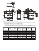
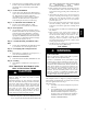
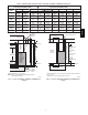
5.1 [130.5] 2 1/16 [51.6] 1.7 [43.5] FRONT OF CASING Ø7/8 [22.2] ACCESSORY (2) 1 15/16 [49.2] 5 15/16 [150.7] 5 1/2 [140.3] 8 7/16 [213.5] 9 7/8 [250.7] 27 3/4 [704.7] 2 5/16 3 7/16 [59] [86.8] 5 7/8 [148.5] TOP OF CASING Ø7/8 [22.2] JUNCTION BOX LOCATION AIR FLOW Ø7/8 [22.2] ACCESSORY Ø1/2 [12.7] THERMOSTAT WIRE ENTRY 5 7/8 [148.5] AIR FLOW 5 7/16 [138.5] A B 6 13/16 [172.3] 5 5/8 [143.3] AIR FLOW 1 15/16 [49.2] 19 [481.7] OUTLET TOP OF CASING 4 13/16 [122.2] 9 9/16 [243.
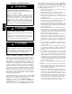
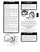
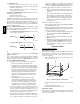
PG8M/J Fig. 2 --- Clearances to Combustibles 80 / 27 C 60 / 16 C A10269 chamber and/or heat exchanger. The furnace is factory--shipped for use with natural gas. This furnace is not approved for installation in mobile homes, recreational vehicles, or outdoors. This furnace is designed for minimum continuous return--air temperature of 60_F (16_C) db or intermittent operation down to 55_F (13_C) db such as when used with a night setback thermostat. Return--air temperature must not exceed 80_F (27_C) db.
National Fuel Gas Code (NFGC) NFPA 54--2012/ANSI Z223.1--2012 and the Installation Standards, Warm Air Heating and Air Conditioning Systems ANSI/ NFPA 90B 2. Step 2 —General Installation S Current edition of the NFGC and the NFPA 90B. For copies, contact the National Fire Protection Association Inc., Batterymarch Park, Quincy, MA 02269; (www.NFPA.org) or for only the NFGC, contact the American Gas Association, 400 N. Capitol Street, N.W., Washington, DC 20001 (www.AGA.org). 3.
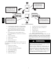
THE BLOWER IS LOCATED BELOW THE BURNER SECTION, AND CONDITIONED AIR IS DISCHARGED UPWARD. PG8M/J THE BLOWER IS LOCATED TO THE RIGHT OF THE BURNER SECTION, AND AIR CONDITIONED AIR IS DISCHARGED TO THE LEFT. THE BLOWER IS LOCATED TO THE LEFT OF THE BURNER SECTION, AND CONDITIONED AIR IS DISCHARGED TO THE RIGHT. THE BLOWER IS LOCATED ABOVE THE BURNER SECTION, AND CONDITIONED AIR IS DISCHARGED DOWNWARD A02097 Fig.
! CAUTION ! WARNING FIRE HAZARD PERSONAL INJURY AND/OR PROPERTY DAMAGE HAZARD Failure to follow this warning could result in personal injury, death and/or property damage. Failure to follow this caution may result in furnace component damage. Do not install the furnace on its back or hang furnace with control compartment facing downward. Safety control operation will be adversely affected. Never connect return--air ducts to the back of the furnace. (See Fig. 6.
f. Size openings and ducts per Fig. 7 and Table 1. g. TWO HORIZONTAL DUCTS require 1 sq./in. of free area per 2,000 Btuh (1,100 mm2/kW) of combined input for all gas appliances in the space per Fig. 7 and Table 1. h. TWO OPENINGS OR VERTICAL DUCTS require 1 sq./in. of free area per 4,000 Btuh (550 mm2/kW) for combined input of all gas appliances in the space per Fig. 7 and Table 1. 3. ONE OUTDOOR OPENING requires: a.
Table 2—Minimum Space Volumes for 100% Combustion, Ventilation, and Dilution from Indoors FAN-ASSISTED TOTAL (1,000’S BTUH GAS INPUT RATE) 30 40 50 110 132 154 1,750 (49.5) 66 88 Space Volume Ft3 (M3) 1,100 1,650 2,200 (31.1) (46.7) (62.2) 0.60 1,050 (29.7) 1,400 (39.6) 2,750 (77.8) 3,300 (93.4) 3,850 (109.0) 0.50 1,260 (35.6) 1,680 (47.5) 2,100 (59.4) 1,320 (37.3) 1,980 (56.0) 2,640 (74.7) 3,300 (93.4) 3,960 (112.1) 4,620 (130.8) 0.40 1,575 (44.5) 2,100 (59.4) 2,625 (74.
PG8M/J The Standard Method: 1. The space has no less volume than 50 cu/ft. per 1,000 Btuh of the maximum input ratings for all gas appliances installed in the space and 2. The air infiltration rate is not known to be less than 0.40 air changes per hour (ACH). The Known Air Infiltration Rate Method shall be used, if the infiltration rate is known to be: 1. Less than 0.40 ACH and 2. Equal to or greater than 0.10 ACH Infiltration rates greater than 0.60 ACH shall not be used.
NOTE: Side return--air openings can be used in UPFLOW and most HORIZONTAL configurations. Do not use side return--air openings in DOWNFLOW configuration. In upflow position with side return inlet(s), leveling legs may be used. (See Fig. 10.) Install field--supplied, 5/16 x 1--1/2 in. (8 x 38 mm) (max) corrosion--resistant machine bolts, washers and nuts. NOTE: Bottom closure must be used when leveling legs are used. It may be necessary to remove and reinstall bottom closure panel to install leveling legs.
FURNACE APPROVED COIL ASSEMBLY OR COIL BOX COMBUSTIBLE FLOORING SHEET METAL PLENUM PG8M/J FLOOR OPENING A08556 Fig. 13 --- Furnace, Plenum, and Coil Assembly or Coil Box Installed on a Combustible Floor Bottom Return Air Inlet These furnaces are shipped with bottom closure panel installed in bottom return--air opening. Remove and discard this panel when bottom return air is used. To remove bottom closure panel, perform the following: 1.
Table 3—Opening Dimensions -- In.
Table 4—Air Delivery -- CFM (with Filter)* PG8M/J FURNACE SIZE RETURN---AIR INLET 045---08/ 024045 Bottom or Side(s) 045---12/ 036045 Bottom or Side(s) 070---08/ 024070 Bottom or Side(s) 070---12/ 036070 Bottom or Side(s) 070---16/ 048070 Bottom or Side(s) 090---14/ 042090 Bottom or Side(s) 090---16/ 048090 Bottom or Side(s) Bottom Only 090---20/ 060090 Both Sides or 1 Side & Bottom 1Side Only 110---12/ 036110 Bottom or Side(s) 110---16/ 048110 Bottom or Side(s) Bottom Only 110---22/
FURNACE SIZE 135---16/ 048135 RETURN---AIR INLET Bottom or Side(s) Bottom Only 135---22/ 066135 Bottom, Sides or 1 Side & Bottom 1 Side Only Bottom Only 155---20/ 060155 Both Sides Or 1 Side & Bottom 1Side Only SPEED High Med --- High Med --- Low High Med --- High Med --- Low High Med --- High Med --- Low High Med --- High Med --- Low High Med --- High Med --- Low High Med --- High Med --- Low High Med --- High Med --- Low 0.
" (6mm) THREADED ROD 4 REQ. 1/4 PG8M/J OUTER DOOR ASSEMBLY SECURE ANGLE IRON TO BOTTOM OF FURNACE WITH 3 #8 x 3/4" (19mm) SCREWS TYPICAL FOR 2 SUPPORTS 8" (203mm) MIN FOR DOOR REMOVAL 1” (25mm) SQUARE, 1-1/4”x1-1/4”x1/8” (32x32x3mm) ANGLE IRON OR UNI-STRUT MAY BE USED (2) HEX NUTS, (2) WASHERS & (2) LOCK WASHERS REQ. PER ROD A10130 Fig. 15 --- Horizontal Unit Suspension METHOD 2 USE (4) #8 x 3/4 (19 mm) SHEET METAL SCREWS FOR EACH STRAP.
LINE CONTACT ONLY PERMISSIBLE BETWEEN LINES FORMED BY INTERSECTIONS OF THE TOP AND TWO SIDES OF THE FURNACE JACKET AND BUILDING JOISTS, STUDS, OR FRAMING. 17 3/4″ (451mm)OVERALL 4 3/4″ (121mm) UNDER DOOR 1″ (25mm) UNDER FURNACE TYPE-B EXTEND OUT 12″ (305mm) VENT FROM FACE OF DOOR ) mm 2 5 1 ( IN* 6″ M 30-IN. (762mm) MIN WORK AREA * WHEN USED WITH SINGLE WALL VENT CONNECTIONS 17 3/4″ (451mm) SHEET METAL 559 22″ ( mm ) EQUIPMENT MANUAL SHUT-OFF GAS VALVE SEDIMENT TRAP UNION Fig.
PG8M/J Fig. 19 --- Downflow Return Air Configurations and Restrictions Fig. 20 --- Horizontal Return Air Configurations and Restrictions Upflow and Horizontal Furnaces Connect supply--air duct to flanges on furnace supply--air outlet. Bend flange upward to 90_ with wide duct pliers. (See Fig. 14.) The supply--air duct must be connected to ONLY the furnace supply--outlet--air duct flanges or air conditioning coil casing (when used).
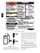
! WARNING FIRE HAZARD Refer to Table 5 for recommended gas pipe sizing. Risers must be used to connect to furnace and to meter. Support all gas piping with appropriate straps, hangers, etc. Use a minimum of 1 hanger every 6 ft. (1.8 M) Joint compound (pipe dope) should be applied sparingly and only to male threads of joints. Pipe dope must be resistant to the action of propane gas. A failure to follow this warning could result in personal injury, or death and/or property damage.
Factory Installed Alternate Location 2” (51mm) PG8M/J Street Elbow Fig. 21 --- Burner and Manifold A08551 Fig. 23 --- Relocating J--Box A10291 GAS SUPPLY MANUAL SHUTOFF VALVE (REQUIRED) SEDIMENT TRAP UNION Fig. 22 --- Typical Gas Pipe Arrangement A02035 Piping should be pressure and leak tested in accordance with NFGC, local, and national plumbing and gas codes before the furnace has been connected.
WARNING ELECTRICAL SHOCK AND FIRE HAZARD Failure to follow this warning could result in personal injury, death, or property damage. The cabinet MUST have an uninterrupted or unbroken ground according to NEC ANSI/NFPA 70--2011 or local codes to minimize personal injury if an electrical fault should occur. This may consist of electrical wire, conduit approved for electrical ground or a listed, grounded power cord (where permitted by local code) when installed in accordance with existing electrical codes.
PG8M/J Table 6—Electrical Data FURNACE SIZE VOLTS--HERTZ--PHASE 045---08/024045 045---12/036045 070---08/024070 070---12/036070 070---16/048070 090---14/042090 090---16/048090 090---20/060090 110---12/036110 110---16/048110 110---22/066110 135---16/048135 135---22/066135 155---20/060155 115--- 60--- 1 115--- 60--- 1 115--- 60--- 1 115--- 60--- 1 115--- 60--- 1 115--- 60--- 1 115--- 60--- 1 115--- 60--- 1 115--- 60--- 1 115--- 60--- 1 115--- 60--- 1 115--- 60--- 1 115--- 60--- 1 115--- 60--- 1 OPERATING
TWINNING AND/OR COMPONENT TEST TERMINAL BLOWER OFF-DELAY J2 JUMPER BLOWER OFF-DELAY 120 180 90 150 J2 HUMIDIFIER TERMINAL (24-VAC 0.5 AMP MAX.) G Com 24V 24-V THERMOSTAT TERMINALS W TRANSFORMER 24-VAC CONNECTIONS PLT Y TEST/TWIN R HUM NUETRAL BLW STATUS CODE LED 3-AMP FUSE PG8M/J 0.5 AMP@24VAC FUSE 3-AMP L2 PL1-LOW VOLTAGE MAIN HARNESS CONNECTOR 1 115-VAC(L2)NEUTRAL CONNECTIONS EAC-2 PL1 LED OPERATION & DIAGNOSTIC LIGHT SEC-2 SEC-1 EAC-1 TERMINAL (115-VAC 1.0 AMP MAX.
PG8M/J 24--V WIRING Make field 24--v connections at the 24--v terminal strip. (See Fig. 25.) Connect terminal Y as shown in Fig. 26 for proper cooling operation. Use only AWG No. 18, color--coded, copper thermostat wire. The 24--v circuit contains an automotive--type, 3--amp. fuse located on the control. Any direct shorts during installation, service, or maintenance could cause this fuse to blow. If fuse replacement is required, use ONLY a 3--amp. fuse of identical size. ACCESSORIES 1.
1. Vent connector is Type--B double--wall, and 2. This furnace is common vented with at least 1 draft hood equipped appliance, and 3. The combined appliance input rating is less than the maximum capacity given in Table 7 , and 4. The input rating of each space heating appliance is greater than the minimum input rating given in Table 8 for the local 99% Winter Design Temperature.
CHIMNEY INSPECTION CHART For additional requirements refer to the National Fuel Gas Code NFPA 54/ANSI Z223.1 and ANSI/NFPA 211 Chimneys, Fireplaces, Vents, and Solid Fuel Burning Appliances Crown condition: Missing mortar or brick? Rebuild crown. Yes PG8M/J No Is chimney property lined with clay tile liner? No Yes Is liner and top seal in good condition? No Repair liner or top seal or reline chimney as necessary.
Air for combustion must not be contaminated by halogen compounds which include chlorides, fluorides, bromides, and iodides. These compounds are found in many common home products such as detergent, paint, glue, aerosol spray, bleach, cleaning solvent, salt, and air freshener, and can cause corrosion of furnaces and vents. Avoid using such products in the combustion--air supply.
Table 7—Exterior Masonry Chimney Fan + Nat Installations with Type--B Double Wall Vent Connectors ENFPA & AGA Combined Appliance Maximum Input Rating in Thousands of Btuh per Hour VENT HEIGHT FT. (M) 6 (1.8) 8 (2.4) 10 (3.0) 15 (4.5) 20 (6.0) 30 (9.1) INTERNAL AREA OF CHIMNEY SQ. IN. (SQ.
FURNACE ORIENTATION VENT ORIENTATION Downflow Vent elbow left, then up Fig. 32 Horizontal Left Horizontal Left Horizontal Left Downflow Downflow Vent elbow right, then up Fig. 35 Vent Elbow up Fig. 36 Vent elbow right Fig. 37 Vent elbow up then left Fig. 30 Vent elbow up, then right Fig. 33 FURNACE INPUT (BTUH/HR) 154,000 132,000 110,000(036/--- 12 only) 154,000 132,000 154,000 132,000 154,000 110,000 (036/--- 12 only) 110,000 (036/--- 12 only) MINIMUM VENT DIAMETER IN.
PG8M/J SEE NOTES: 1,2,4,5,6,7,8,9,10 on the page following these figures SEE NOTES:1,2,3,4,5,7,8,9 on the page following these figures A03210 A03207 Fig. 30 --- Downflow Application--Vent Elbow Up then Left Fig. 32 --- Downflow Application--Vent Elbow Left then Up SEE NOTES:1,2,3,4,5,7,8,9 on the page following these figures. SEE NOTES: 1,2,4,5,7,8,9 on the page following these figures Fig. 31 --- Downflow Application--Vent Elbow Up A03211 A03212 Fig.
SEE NOTES: 1,2,4,7,8,9 on the page following these figures SEE NOTES: 1,2,4,5,7,8,9 on the page following these figures A03214 A03218 Fig. 38 --- Horizontal Right Application--Vent Elbow Right PG8M/J Fig. 35 --- Horizontal Left Application--Vent Elbow Right then Up SEE NOTES: 1,2,4,5,7,8,9 on the page following these figures SEE NOTES: 1,2,4,5,7,8,9 on the page following these figures A03219 A03215 Fig. 39 --- Horizontal Right Application--Vent Elbow Left then Up Fig.
START--UP, ADJUSTMENT, AND SAFETY CHECK Step 1 —General ! ! WARNING ELECTRICAL SHOCK HAZARD Failure to follow this warning could result in personal injury, or death. FIRE HAZARD PG8M/J Failure to follow this warning could result in personal injury, death and/or property damage. This furnace is equipped with manual reset limit switches in the gas control area. The switches open and shut off power to the gas valve if a flame rollout or overheating condition occurs in the gas control area.
8001–9000 32–36 0.66 (2438 ---2743) 9001–10,000 36–40 0.62 (2743 ---3048) * Derate multiplier factors are based on midpoint altitude for altitude range. WARNING FIRE HAZARD Failure to follow this warning could result in injury, death and/or property damage. DO NOT bottom out gas valve regulator adjusting screw. This can result in unregulated manifold pressure and result in excess overfire and heat exchanger failures.
b. When thermometer readings stabilize, subtract return-air temperature from supply--air temperature to determine air temperature rise. NOTE: Blower access door must be installed for proper temperature rise measurement. NOTE: If the temperature rise is outside this range, first check: S S S Gas input for heating operation. S Dirty filter. Failure to follow this caution may result in reduced furnace life. Recheck temperature rise. It must be within limits specified on the rating plate.
PG8M/J Fig.
PG8M/J BURNER ORIFICE Fig. 42 --- Gas Control Valve A06666 Fig. 43 --- Orifice Hole A93059 THERMOSTAT SUBBASE TERMINALS WITH THERMOSTAT REMOVED (ANITICIPATOR, CLOCK, ETC., MUST BE OUT OF CIRCUIT.) HOOK-AROUND AMMETER R Y W G 10 TURNS FROM UNIT 24-V CONTROL TERMINALS EXAMPLE: 5.0 AMPS ON AMMETER 10 TURNS AROUND JAWS = 0.5 AMPS FOR THERMOSTAT ANTICIPATOR SETTING Fig. 44 --- Amp.
The flame sensor, gas valve, and pressure switch were all checked in the Start--up procedure section as part of normal operation. 1. Check Main Limit Switch(es) This control shuts off combustion control system and energizes air--circulating blower motor, if furnace overheats. By using this method to check limit control, it can be established that limit is functioning properly and will operate if there is a restricted duct system or motor failure.
PG8M/J Table 12—Gas Rate (cu ft.
ALTITUDE RANGE FT. (M) U.S.A. U.S.A. 0 to 2000 (0 to 610) 2001 to 3000 (610 to 914) U.S.A. 3001 to 4000 (914 to 1219) U.S.A. 4001 to 5000 (1219 to 1524) AVG. GAS HEAT VALUE AT ALTITUDE (BTU/CU FT.) 900 925 950 975 1000 1025 1050 1075 1100 800 825 850 875 900 925 950 975 1000 775 800 825 850 875 900 925 950 750 775 800 825 850 875 900 925 0.58 Orifice Manifold No. Pressure 42 3.5 42 3.3 43 3.8 43 3.6 43 3.5 43 3.3 44 3.6 44 3.4 44 3.3 42 3.4 42 3.2 43 3.7 43 3.5 43 3.3 43 3.1 43 2.9 43 2.8 43 2.
Table 14–Orifice Size* and Manifold Pressure (In. W.C.) for Gas Input Rate (Continued) (Tabulated data based on 22,000 btuh per burner, derated 4 percent for each 1000 ft. (305 M) above sea level) ALTITUDE RANGE FT. (M) PG8M/J U.S.A. U.S.A. U.S.A. U.S.A. U.S.A. 5001 to 6000 (1524 to 1829) 6001 to 7000 (1829 to 2134) 7001 to 8000 (2134 to 2438) 8001 to 9000 (2438 to 2743) 9001 to 10,000 (2743 to 3048) SPECIFIC GRAVITY OF NATURAL GAS AVG. GAS HEAT VALUE AT ALTITUDE (BTU/CU FT.) Orifice No.
Table 15—Orifice Size* and Manifold Pressure (In. W.C.) for Gas Input Rate (Tabulated data based on 21,000 btuh per burner, derated 4 percent for each 1000 ft. (305 M) above sea level) U.S.A. 0 to 2000 (0 to 610) U.S.A. 2001 to 3000 (610 to 914) U.S.A. 3001 to 4000 (914 to 1219) U.S.A. 4001 to 5000 (1219 to 1524) SPECIFIC GRAVITY OF NATURAL GAS AVG. GAS HEAT VALUE AT ALTITUDE (BTU/CU FT.
Table 15—Orifice Size* and Manifold Pressure (In. W.C.) for Gas Input Rate (Continued) (Tabulated data based on 21,000 btuh per burner, derated 4 percent for each 1000 ft. (305 M) above sea level) PG8M/J ALTITUDE RANGE FT. (M) U.S.A. 5001 to 6000 (1524 to 1829) U.S.A. 6001 to 7000 (1829 to 2134) U.S.A. 7001 to 8000 (2134 to 2438) U.S.A. 8001 to 9000 (2438 to 2743) U.S.A. 9001 to 10,000 (2743 to 3048) SPECIFIC GRAVITY OF NATURAL GAS AVG. GAS HEAT VALUE AT ALTITUDE (BTU/CU FT.) Orifice No.
SERVICE If status code recall is needed, briefly remove then reconnect one main limit wire to display stored status code. On RED LED boards do not remove power or blower door before initiating status code recall. After status code recall is completed component test will occur. LED CODE STATUS CONTINUOUS OFF - Check for 115VAC at L1 and L2, and 24VAC at SEC-1 and SEC-2. CONTINUOUS ON - Control has 24VAC power. RAPID FLASHING - Line voltage (115VAC) polarity reversed.
PG8M/J The control system also requires an earth ground for proper operation of the control and flame--sensing electrode. The 24--v circuit contains an automotive--type, 3--amp. fuse located on the control. (See Fig. 25.) Any shorts of the 24--v wiring during installation, service, or maintenance will cause this fuse to blow. If fuse replacement is required, use ONLY a 3--amp. fuse. The control LED will display status code 24 when fuse needs to be replaced.
CAUTION CUT HAZARD Failure to follow this caution may result in personal injury. Sheet metal parts may have sharp edges or burrs. Use care and wear appropriate protective clothing, safety glasses and gloves when handling parts and servicing furnaces. Media cabinet filter procedures: NOTE: Media cabinet or 3/4--in. (19 mm) filter rack are accessories and are not included from the factory. 1. Turn off electrical supply to furnace before removing filter access door. 2. Remove filter cabinet door. 3.
PG8M/J NOTE: If thermostat terminals are jumpered at the time blower access door switch is closed, blower will run for 90 sec before beginning a heating or cooling cycle. c. Perform component self--test as shown at the bottom of the SERVICE label, located on the front of blower access door. d. Verify blower is rotating in the correct direction 16. If furnace is operating properly, RELEASE BLOWER ACCESS DOOR SWITCH. Remove any jumpers or reconnect any disconnected thermostat leads.
14. 15. 1-7/8 (47.6 mm) 16. 17. 18. Fig. 47 --- Igniter Position--Top View A05026 i. Install NOx baffles (if removed). Reinstall internal vent pipe, if applicable. Reinstall vent connector on furnace vent elbow. Securely fasten vent connector to vent elbow with 2 field--supplied, corrosion--resistant, sheet metal screws located 180_ apart. Replace blower access door only, if it was removed. Set thermostat above room temperature and check furnace for proper operation.
PG8M/J gized until the flame is sensed or until the 2--second flame proving period begins. d. Flame--Proving-- When the burner flame is proved at the flame--proving sensor electrode FSE, the furnace control CPU begins the blower--ON delay period and continues to hold the gas valve GV open.
Fig. 49 --- Troubleshooting Guide 49 YES Go to section below for the status code that was flashed. Determine status code.
24 SECONDARY VOLTAGE FUSE IS OPEN Check for: - Short circuit in secondary voltage (24V) wiring including thermostat leads. Disconnect thermostat leads to isolate short circuit. 23 PRESSURE SWITCH DID NOT OPEN Check for: - Obstructed pressure tube. - Pressure switch stuck closed. 22 ABNORMAL FLAME-PROVING SIGNAL Flame is proved while gas valve is deenergized. Inducer will run until fault is cleared. Check for: - Stuck open or leaky gas valve.
I M