
Use and Care Manual
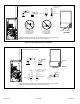
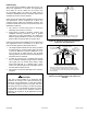
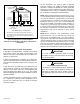
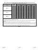
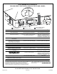
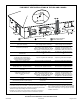
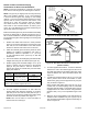
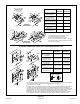
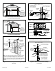
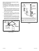
Table Of Contents
- Unit Dimensions
- Parts Arrangement
- Gas Furnace
- Shipping and Packing List
- Safety Information
- General
- Combustion, Dilution & Ventilation Air
- Installation
- Filters
- Duct System
- Venting Practices
- Condensate Piping
- Gas Piping
- Electrical
- Unit Start-Up
- Testing for Proper Venting and Sufficient Combustion Air for Non-Direct Vent Applications
- Other Unit Adjustments
- Blower Performance Data
- Service
- Planned Service
- Repair Parts List

507769C05 Page 23 of 55
mrcool.com
Maximum Allowable Exhaust Vent Pipe Length
3
(in ft.) without Insulation in Unconditioned Space for Winter Design
Temperatures Single - Stage High Eciency Furnace
Winter Design Temperatures
1
ºF (ºC)
Vent Pipe
Diameter
Unit Input Size
045 070 090 110
32 to 21
(0 to -6)
PVC
2
PP PVC
2
PP PVC
2
PP PVC
2
PP
1-1/2 in. 20 N/A 20 N/A N/A N/A N/A N/A
2 in. 18 16 31 28 50 48 30 30
2-1/2 in. 13 N/A 24 N/A 42 N/A 36 N/A
3 in. 9 9 18 18 35 35 29 29
20 to 1
(-7 to -17)
1-1/2 in. 15 N/A 20 N/A N/A N/A N/A N/A
2 in. 9 8 18 16 32 29 27 24
2-1/2 in. 5 N/A 13 N/A 24 N/A 20 N/A
3 in. 1 1 8 8 19 19 14 14
0 to -20
(-18 to -29)
1-1/2 in. 10 N/A 15 N/A N/A N/A N/A N/A
2 in. 5 3 12 10 22 19 18 15
2-1/2 in. 1 N/A 7 N/A 15 N/A 12 N/A
3 in. N/A N/A 2 2 10 10 7 7
1
Refer to 99% Minimum Design Temperature table provided in the current edition of the ASHRAE Fundamentals Handbook.
2
Poly-Propylene vent pipe (PP) by Duravent and Centrotherm
3
Vent length in table is equivalent length. Each elbow is equivalent to 5ft of straight pipe and should be included when measuring
total length.
NOTE - Concentric terminations are the equivalent of 5’ and should be considered when measuring pipe length.
NOTE - Maximum uninsulated vent lengths listed may include the termination (vent pipe exterior to the structure ) and cannot exceed
5 linear feet or the maximum allowable intake or exhaust vent length listed in Table 7A through Table 7D or Table 8A through Table
8B.
NOTE - If insulation is required an unconditioned space, it must be located on the pipe closed to the furnace.
Table 9.