
Installation Guide


35
I&O manual
12 SAFETY CIRCUIT DESCRIPTION
12.1 General
A number of safety circuits are employed to ensure safe and proper
furnace operation. These circuits serve to control any potential
safety hazards and serve as inputs in the monitoring and diagnosis
of abnormal function. These circuits are continuously monitored
during furnace operation by the integrated control module.
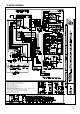
12.2 Integrated Control Module
The integrated control module is an electronic device which
controls all furnace operations. Responding to the thermostat,
the module initiates and controls normal furnace operation,and
monitors and addresses all safety circuits. If a potential safety
concern is detected, the module will take the necessary
precautions and provide diagnostic information through an LED.
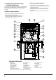
12.3 Primary Limit
The primary limit control is located on the partition panel and
monitors heat exchanger compartment temperature. It is an
automatic reset, temperature sensor. The limit guards against
the overheating resulting from insufficient air passing over the
heat exchanger.
12.4 Rollout Limits
12.5 Overflow protection pressure switch
(Overflow switch)
The rollout limit controls are mounted on the burner/manifold
assembly and monitor the burner flame. They are manual-reset,
temperature sensors. This limit guards against burner flames
not being properly drawn into the heat exchanger.
12.6 Pressure Switches
The pressure switches are normally-open, negative air pressure-
activated switches. They monitor the airflow (combustion air and
flue products) through the heat exchanger via pressure taps located
on the induced draft blower. These switches guard against insufficient
airflow (combustion air and flue products) through the heat exchanger.
Overflow switch is a differential pressure switch. The shape and
dimension of overflow switch is similar to two other pressure switches
except it has two pressure ports, one in gray color (negative) and the
other in black color (positive). The overflow switch is normally closed.
When condensate hoses or trap is blocked and condensate is stopped
flowing to drain system, the level of condensate inside condensate
collector box will rise to certain point. When condensate reaches
certain level in condensate collector box, overflow switch will open
and shut off the furnace. Make sure that black port (positive) is conn-
ected to the lower position tap on condensate collector box and gray
port (negative) to higher tap of condensate box.
Manufacturer’s default setting is for installations on upflow and horiz-
ontal right only. For horizontal left installation, hoses for overflow
switch are required to switch (see horizontal left installation).Conn-
ecting hoses incorrectly will result in failure to protect condensate
overflow.
12.7 Flame Sensor
The flame sensor is a probe mounted to the burner/manifold
assembly which uses the principle of flame rectification to determine
the presence or absence of flame.
13 TROUBLESHOOTING
13.1 Electrostatic Discharge (Eso) Precautions
NOTE: Discharge body's static electricity before touching unit. An
electrostatic discharge can adversely affect electrical components.
Use the following precautions during furnace installation and
servicing to protect the integrated control module from damage.
By putting the furnace, the control, and the person at the same
electrostatic potential, these steps will help avoid exposing the
integrated control module to electrostatic discharge. This
procedure is applicable to both installed and uninstalled
(ungrounded) furnaces.
1. Disconnect all power to the furnace. Do not touch the
integrated control module or any wire connected to the control
prior to discharging your body's electrostatic charge to ground.
2. Firmly touch a clean, unpainted, metal surface of the
furnace away from the control. Any tools held in a person's
hand during grounding will be discharged.
3. Service integrated control module or connecting wiring
following the discharge process in step 2. Use caution
not to recharge your body with static electricity; (i.e., do not
move or shuffle your feet, do not touch ungrounded objects,
etc.). If you come in contact with an ungrounded object,
repeat step 2 before touching control or wires.
4. Discharge your body to ground before removing a new
control from its container. Follow steps 1 through 3 if
installing the control on a furnace. Return any old or new
controls to their containers before touching any ungrounded
object.The primary limit control is located on the partition panel and
13.2 Diagnostic Chart
Refer to the troubleshooting chart on the following pages for
assistance in determining the source of unit operational problems.
The red diagnostic LED blinks to assist in troubleshooting the unit.
The number of blinks refer to a specific code.(See Table 16)
13.3 Resetting From Lockout
Furnace lockout results when a furnace is unable to achieve ignition
after three attempts. It is characterized by a non-functioning furnace
and a one flash diagnostic LED code from the red LED. If the furnace
is in "lockout",it will (or can be) reset in any of the following ways.
1. Automatic reset. The integrated control module will
automatically reset itself and attempt to resume normal
operations following a one hour lockout period.
2. Manual power interruption. Interrupt 115 volt power to the
furnace for at least 20 seconds.
3. Manual thermostat cycle. Lower the thermostat so that
there is no longer a call for heat for 1 - 20 sec
NOTE: If the condition which originally caused the lockout
still exists, the control will return to lockout. Refer to the
diagnostic Chart for aid in determining the cause.
WARNING
Failure to replace with proper control could result in fire,
explosion or carbon monoxide poisoning.
This appliance uses a NEGATIVE PRESSURE REGULATED
gas control.
Replace ONLY with the same model number or as specified by
the manufacturer.
FIRE,EXPLOSION OR CARBON MONOXIDE
POISONING HAZARD
WARNING
Improper adjustment, alteration, service, maintenance or
installation can cause serious injury or death.
Read and follow instructions and precaution in User’s
information Manual provided with this furnace.
Installation and service must be performed by a qualified
service agency or the gas supplier.
FIRE,EXPLOSION AND ASPHYXIATION HAZARD