
Installation Guide


39
I&O manual
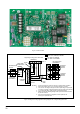
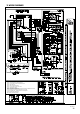
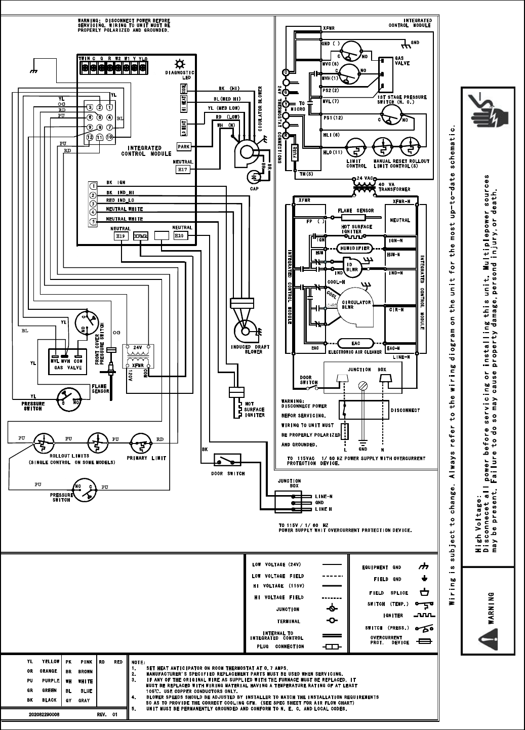
15 WIRING DIAGRAMS
4
5
E1 7
E1 9
3
OG
XFM R
E2 0
PU
BR
RD
RD
BR
PU
PU
BL
BL
BR
BR
BR
OG
GR
PU
PU
PU
PU
RD
10
3
H
I
H
E
A
T
L1
L1
W1
W2
YLO
BK
WH
WH
(9)
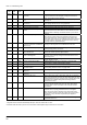
1 Flash = Flame sensed when no flame should be present
2 Flash = Pressure switch stuck closed/ inducer error
3 Flash = 1st-stage pressure switch stuck open/inducer error
4 Flash = Open limit switch
5 Flash = Open rollout/open fuse detect
6 Flash = 1st-stage pressure switch cycle lockout
7 Flash = External lockout (retries)
8 Flash = External lockout (ignition recycles exceeded where flame is established and then lost)
9 Flash = Grounding or Reversed polarity
10 Flash = Module gas valve contacts energized with no call for heat
11 Flash = Limit switch open – possible blower failure overheating limit
12 Flash = Module Ignitor contact failure
Solid = Module - internal fault condition
GR
G/ Y