
Installation Guide


32
I&O manual
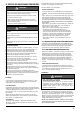
10.4 Sequence of Operation
3. FAN Mode
2. Cooling Mode
If the thermostat fan switch is moved to the ON position, the
circulator fan (low heat speed) and the electronic air cleaner
(optional) are energized. When the fan switch is returned to
the AUTO position, the circulator and electronic air cleaner are
de-energized.
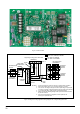
NOTE: Furnace control must be grounded for proper operation or
control will lock out. Control is grounded through green wire routed to
gas valve and manifold bracket screw. follow the sequence of
operation through the different modes.
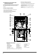
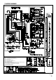
Read and follow the wiring diagram very carefully.
The blower door must be installed for power to be conducted through
the blower door interlock switch to the furnace control CPU,
transformer , inducer motor, blower motor , hot--surface igniter , and
gas valve .
1. Heating mode
In a typical system, a call for first stage heat is initiated by closing the
W1 thermostat contacts. The inducer blower is energized at high
speed and the control waits for the low pressure switch contacts to
close. The humidifier (optional) is also energized at this time. Once
the low pressure switch contacts close, a 15-second pre-purge is
initiated. Then the inducer changes to low speed and the 120V ignitor
is powered. At the end of the ignitor warm-up time, the first stage of
the two-stage manifold gas valve is energized (low fire). Flame must
be detected within 4 seconds. If flame is detected, the 45-second
HEAT delay-to-fan-on period begins. After the delay-to-fan-on period
ends, the control will energize the circulator fan at low heat speed.
The electronic air cleaner (optional) will also energize at this time.
For a two-stage thermostat, a call for second stage heat (W1 and W2)
after a call for first stage heat will energize the inducer at high speed
and the circulator at high heat speed. The second stage pressure
switch contacts will close and energize the second stage gas valve
(high fire). For a single-stage thermostat, when a call for heat occurs
(W1), a 10, 20 minute or auto mode heat staging timer will be
activated (timing is selectable with option switches S1-1 and S1-2
positions). Following this delay, the second stage heat is energized as
above. The AUTO model algorithm is a method of energizing the
second stage gas valve based on the recent average of the heating
duty cycle. During a typical heating day, the low to high stage delay
is determined by using the average calculated duty cycle from the
table below. Once the specified delay time has expired the second
stage valve will be energized. See the table below for the different
duty cycles.
When the second stage of the thermostat is satisfied, the inducer
motor is reduced to low speed and the second stage gas valve is
de-energized.On the control, the circulator will remain at high heat
speed for 30 seconds following the opening of the second stage gas
valve and then is reduced to low heat speed. When the first stage of
the thermostat is satisfied, the first stage gas valve is de-energized
and the HEAT delay-to-fan-off begins timing. The inducer will
postpurge for an additional 15 seconds, then the inducer and
humidifier will turn off. Upon completion of the HEAT delay-to-fan-off
period, the circulator is turned off. The electronic air cleaner on the
control is also de-energized at this time.
If flame is not detected during the trial-for-ignition period or if the flame
is detected/sensed and then lost before completion of 10 seconds of
establishment, the gas valve is de-energized, the ignitor is turned off,
and the control goes into the “retry” sequence. The “retry” sequence
provides a 60-second wait with the inducer interpurge following an
unsuccessful ignition attempt (flame not detected). After this wait, the
ignition attempt is restarted. Two retries will be attempted before the
control goes into system lockout. If flame is established for more than
10 seconds after ignition, the controller will clear the ignition attempt
(or retry) counter. If flame is lost after 10 seconds, the control will
restart the ignition sequence.
A momentary loss of gas supply, flame blowout, or a shorted or
open condition in the flame probe circuit will be sensed within 2.0
seconds. The gas valve will de-energize and the control will
restart the ignition sequence. Recycles will begin and the burner
will operate normally if the gas supply returns, or the fault
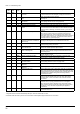
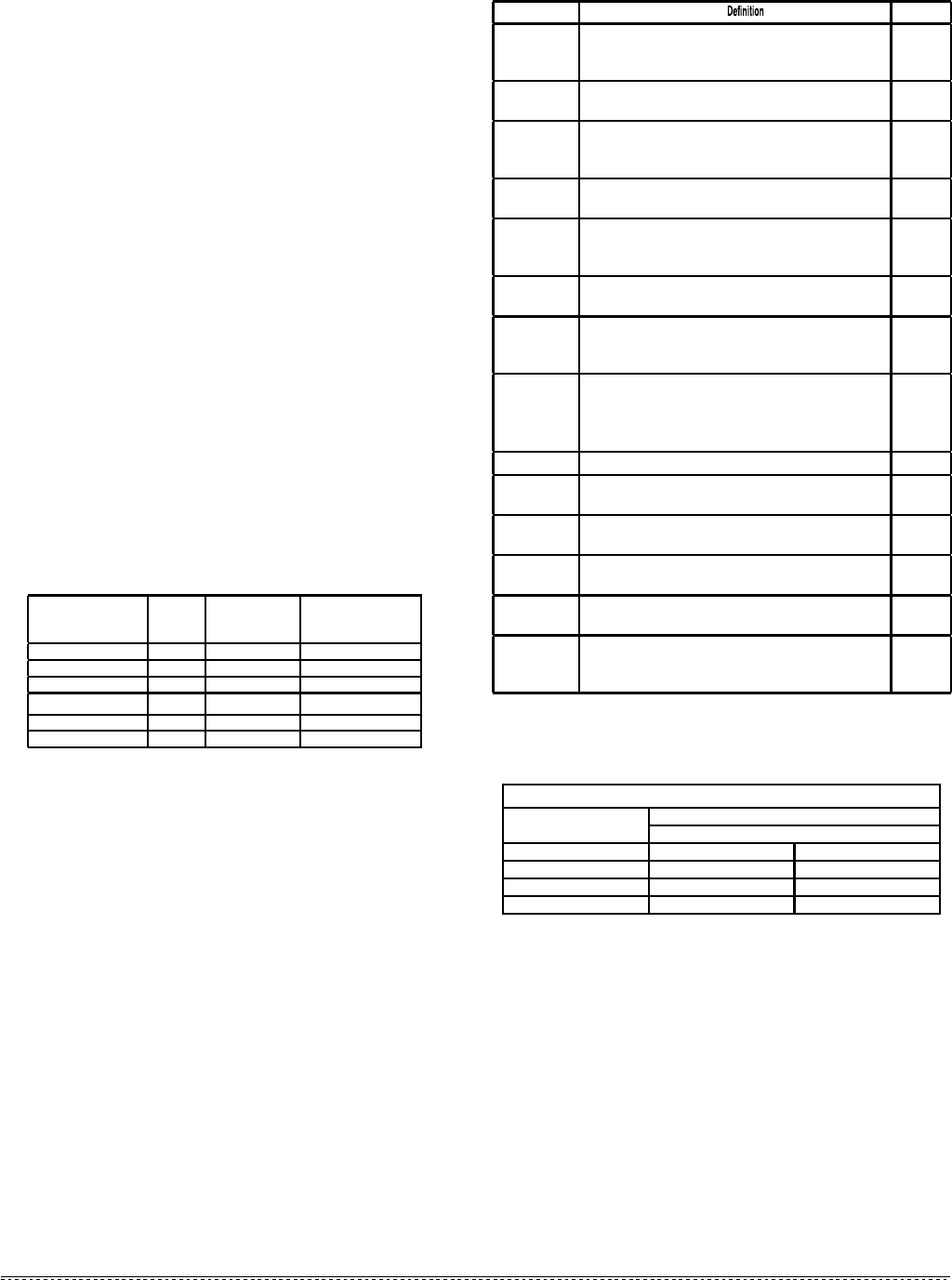
TIMING SPECIFICATIONS
(All times are in seconds, unless noted otherwise)
condition is corrected, before the last ignition attempt. Otherwise,
the control will go into system lockout. If the control has gone into
system lockout, it may be possible to reset the control by a
momentary power interruption of 10 seconds or longer.
Refer to SYSTEM LOCKOUT AND DIAGNOSTIC FEATURES.
Average
Calculated Duty
Cycle % Equals
Or less
than
Low to High
Stage Delay
Demand
0 38 12 minutes Light
38 50 10 minutes Light to Average
50 62 7 minutes Average
62 75 5 minutes Average to Heavy
75 88 3 minutes Heavy Light
88 100 1 minute Heavy
Event 50M51-843
Pre-purge Time The period of time intended to allow for the dissipation of any
unburned gas or residual products of combustion at the beginning
of a furnace operating cycle prior to initiating ignition
15
Igniter Warm-up
Time
The length of time allowed for the igniter to heat up prior to the
initiation of gas flow.
17
Trial for Ignition
Period (TFI)
The period of time between initiation of gas flow and the action to
shut off the gas flow in the event of failure to establish proof of the
supervised ignition source or the supervised main burner flame.
4
Ignition Activation
Period (IAP)
The period of time between energizing the main gas valve and
deactivation of the ignition means prior to the end of TFI
3
Retries The additional attempts within the same thermostat cycle for
ignition when the supervised main burner flame is not proven
within the first trial for ignition period.
2 times
Valve Sequence
period
Valve sequence period equals 4 seconds trial for ignition
period x (1 initial try + 2 retries) + 12 seconds.
12
Inter-purge The period of time intended to allow for the dissipation of any
unburned gas or residual products of combustion between the
failed trial for ignition and the retry period.
60
Post-purge Time
The period of time intended to allow for the dissipation of any
unburned gas or residual products of combustion at the end of a
furnace burner operating cycle. Post-purge begins at the loss
of flame sense.
15
Lock-Out Time ANSI standard rated module timing. 300
Heat Delay-To-
Fan-On
The period of time between proof of the supervised main burner
flame and the activation of the blower motor at Heat speed.
45
Heat Delay-To-
Fan-Off*
The period of time between the loss of a call for heat and the
deactivation of the blower motor at Heat speed.
90/120/
150/180
Cool Delay-To-
Fan-On
The period of time after a thermostat demand for cool before
energizing the circulator blower motor at Cool speed.
5
Cool Delay-To-
Fan-Off
The period of time between the loss of a call for cool and the
deactivation of the blower motor at Cool speed.
60
Automatic Reset
Time
After one (1) hour of internal or external lockout, the control will
automatically reset itself and go into an auto restart purge for 60
seconds.
60
minutes
*These times will vary depending on option switch position.
When using a single stage thermostat, second stage delay is
based on the setting of switch S1-1, S1-2 shown below.
OPTION SWITCHES S1-1 & S1-2 POSITIONS
*Factory default setting– two stage thermostat
2nd Stage delay for single stage thermostats
Delay Time:
On "S1" set switch #
1 2
Off* Off Off
10 min On Off
Auto min Off On
20 min On On
In a typical single stage cooling system (Y connection), a call
for cool is initiated by closing the thermostat contacts. This
energizes the compressor and the electronic air cleaner
(optional).
The circulator will be energized at cool speed after the COOL
delay-to-fan-on period. After the thermostat is satisfied, the
compressor is de-energized and the COOL delay-to-fan-off
period begins. After the COOL delay-to-fan-off period ends,
the circulator and the electronic air cleaner are de-energized.