
Installation Guide
26
I&O manual
8.4 Gas Piping Connections
When sizing a trunk line, be sure to include all appliances which
will operate simultaneously.(See Table 13)
The gas piping supplying the furnace must be properly sized based
on the gas flow required, specific gravity of the gas, and length of
the run. The gas line installation must comply with local codes, or
in their absence,Refer to the latest version of NFPA54/ANSI Z223.1
for US and the latest version of CSA B149.1 for Canada.
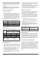
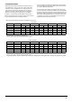
Table 13-NaturalGas Capacity of Pipe In Cubic Feet of Gas Per Hour (CFH)
(Pressure 0.5 psig or less and pressure drop of 0.3" W.C.; Based on
0.60 Specific GravityGas)
CFH=
BTUH Furnace input
Heating Value of Gas (BTU/Cubic Foot)
Internal
DIA.
in.(mm)
Nominal
iron pipe
size
in.(mm)
Length of pipe-ft(m)
10
(3.0)
1/2(12.7)
0.622(15.8)
0.824(20.9)
1.049(26.6)
1.380(35.0)
1.610(40.9)
175 120 97 82 73
360 250 200 170 151
680 465 375 320 285
1400 950 770 660 580
2100 1460 1180 990 900
3/4(19.0)
1(25.4)
1-1/4(31.8)
1-1/2(38.1)
20
(6.0)
30
(9.1)
40
(12.1)
50
(15.2)
To connect the furnace to the building's gas piping, the installer
must supply a ground joint union, drip leg, manual shutoff valve,
and line and fittings to connect to gas valve. In some cases, the
installer may also need to supply a transition piece from 1/2" pipe
to a larger pipe size.
To avoid possible unsatisfactory operation or equipment damage due
to underfiring of equipment, use the proper size of naturaupropane
gas piping needed when running pipe from the meter/tank to the
furnace.
The gas supply shall be shut off prior to disconnecting the electrical
power before proceeding with conversion
1.Make sure all utilities (gas and electricity) are turned off
2.Remove the furnace front panel
3.Disconnect the gas line from the gas valve
4.Disconnect the wires at gas control.
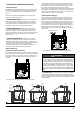
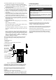
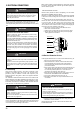
To Replace Orifices with LP Orifices From Gas Manifold:
See Fig.29.
1.Disconnect all control wires
2.Remove 4 screws holding gas manifold to supporting burner
assembly bracket
3.Slide the manifold (with valve and orifices) out of burners. Be careful
not to damage the assembly.
4.Replace the natural gas orifices with the LP orifices or appropriate
high altitude orifices (refer to Section High Altitude Installation)
5.Re-assemble the gas manifold and re-connect all wires.
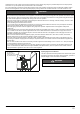
To Convert From Natural to LP Gas on Gas Valve
1.Remove regulator (gas valve) cover screw
2.Remove regulator adjustment screw (beneath the cover screw)
3.Remove natural gas spring from regulator sleeve.
4.Insert the LP spring included in the conversion kit into sleeve
5.Replace the adjustment screw and adjust the outlet pressure to
manufacturer’s specified outlet pressure (Refer to Fig 34 and Section
10.5 and 10.6 for outlet pressure tap location and pressure
measurement)
6.Replace the regulator cover screw
7.Attach the WARNING label (provided in the kit) to the gas valve,
attach small round LP label to the top of regulator cover screw.
8.Fill required blanks in provided conversion label and attach it to
appropriate location on furnace case.
8.3 Propane Gas Conversion
Possible property damage, personal injury or death may occur if the
correct conversion kits are not installed. the appropriate kits must be
applied to insure safe and proper furnace operation. all conversions
must be performed by a qualified installer or service agency.
This unit is configured for natural gas. The appropriate manufacturer's
propane gas conversion kit , must be applied for propane gas installa-
tions. High Altitude Installations refer to the "High Altitude Derate"
section for details.
Contact your distributor for a tabular listing of appropriate
manufacturer's kits for propane gas and/or high altitude installations.
The indicated kits must be used to insure safe and proper furnace
operation. All conversions must be performed by a qualified installer,
or service agency.
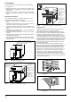
on/off Lever
Gas Valve
Inlet
Gas Manifold
Burner Orifices
Burner Box
Fig. 29
de-energized.