
Installation Guide
22
I&O manual
In unconfined spaces (see definition below) in buildings, infiltration may
be adequate to provide air for combustion ventilation and dilution of flue
gases. However, in buildings of tight construction (for example, weather
stripping, heavily insulated, caulked, vapor barrier, etc.), additional air
may need to be provided using the methods described in “An confined
space” section.
An
confined space
is an area with less than 50 cu . ft (1.42m
3
) per
1,000 Btu/hr (0.2928 kW) input rating for all of the appliances installed in
that area. The following must be considered to obtain proper air for
combustion and ventilation in confined spaces.
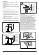
Air Supply Openings and Ducts
Combustion Air Source from Outdoors
1. Two permanent openings, one within 12 in (305 mm) of the top
and one within 12 in (305 mm) of bottom of the confined space,
Two permanent openings, shall communi cate directly or by means
of ducts with the outdoors, crawl spaces or attic spaces.
2. One permanent openings, commencing within 12 in (305 mm)of
the top of the enclosure shall be permitted where the equipment
has clearances of at least 1 in (25.4 mm) from the sides and back
and 6 in (152.4 mm) from the front of the appliance. The opening
shall communicate directly with the outdoors and shall have a min-
imum free area of:
a. 1 square in per 3000 Btu per hour (734 mm2/kW) of the total
input rating of all equipment located in the enclosure.
b. Not less than the sum of all vent connectors in the confined
space.
3. The duct shall be least the same
cross-sectional area as the free
area of the air supply inlet opening to which it connects.
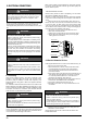
4. The blocking effects of louvers, grilles and screens must be given
consideration in calculating free area. If the free area of a specific
louver aor grille is not known. Refer to Table ,“Estimated Free
Area” to estimated free area.
Table 10 : Estimated Free Area
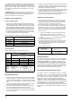
Ventilated Combustion Air
The ventilated attic space or a crawl space from which the combustion
air is taken must comply with the requirements specified in “
Combustion
Air Source from Outdoors
” in this instruction or in Section 7.4, Air
for Combustion and Ventilation of the National Fuel Gas Code, ANSI
Z223.1 (latest edition). This type in stallation requires two properly sized
pipes. One brings combustion air from
a properly ventilated attic space
or crawl space and a second pipe that extends from the furnace vent
connection (top right of unit) to the exterior of the building.
Wood or Metal
Louvers or Grilles
Wood 20-25%
Metal 60-70%
Screens +
1/4” (0.635cm)
mesh or larger 100%
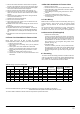
Table 9 : Minimum Free Area Required for Each Opening
b) All air from outdoors:
BTUH Input
Rating
Minimum Free Area Required for Each Opening
Horizontal Duct
(2,000 BTUH)
Vertical Duct or
Opening to Outside
(4,000 BTUH)
Round Duct
(4,000 BTUH)
60,000
30 in
2
(193 cm
2
)
2
(97 cm
2
)
5” (13 cm)
100,000
50 in
2
(322 cm
2
)
2
(161 cm
2
)
6” (15 cm)
80,000
40 in
2
(258 cm )
2
20 in
15 in
25 in
30 in
2
(129 cm
2
)
5” (13 cm)
120,000
60 in
2
(387 cm
2
)
2
(194 cm
2
)
7” (18 cm)
EXAMPLE: Determining Free Area.
Appliance 1 Appliance 2 Total Input
100,000 + 30,000 = (130,000
4,000) = 32.5 Sq. In. Vertical
Appliance 1 Appliance 2 Total Input
100,000 + 30,000 = (130,000
2,000) = 65 Sq. In. Horizontal
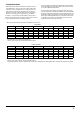
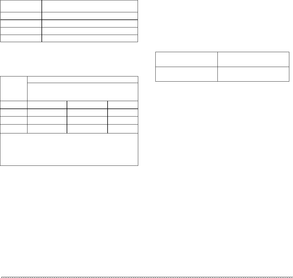
Table 8 : Minimum Area in Square Inch Required for Each Opening
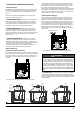
a) All air from inside the building:
The confined space shall be provided with two permanent openings
communicating directly with an additional room(s) of sufficient volume
so that the combined volume of all spaces meets the criteria. The total
input of all gas utilization equipment installed in the combined space
shall be considered in making this determination. Each opening shall
have a minimum free area of 1 square inch per 1,000BTU per hour of
the total input rating of all gas utilization equipment in the confined sp-
ace. One opening shall be within 12 inches of the top and one within
12 inches of the bottom of the enclosure (See Table 8).
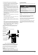
Equipment Located in Confined Spaces:
Vent and Supply (Outside) Air Safety Check Procedure
BTUH Input Rating
Minimum Free Area in Square Inch
Required for Each Opening
80 in (516 cm
2 2
) 100 in (645 cm
2
2
)
120 in (742 cm
2
2
)
80,000
60 in (387 cm
2 2
)
60,000
100,000
120,000
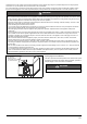
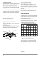
An opening may be used in lieu of a duct to provide to provide the
outside air supply to an appli ance unless otherwise permitted by
the authority having jurisdiction. The opening shall be located
within 12” (30.5 cm) horizontally from, the burner level of the appli-
ance.
The duct shall be either metal, or a material meeting the class 1
requirements of CAN4-S110 Standard for Air Ducts.
The duct shall be least the same cross-sectional area as the free
area of the air supply inlet opening to which it connects.
The duct shall terminate within 12 in (30.5 cm) above, and within
24 in (61 cm) horizontally from, the burner level of the appliance
having the largest input.
5. A square or rectangular shaped duct shall only be used when the
required free area of the supply opening is 9 in
2
(58.06 cm
2
) or
larger. When a square or rectangular duct is used, its small dimen-
sion shall not be less than 3 in (7.6 cm).
6. An air inlet supply from outdoors shall be equipped with a means
to prevent the direct entry of rain and wind. Such means shall not
reduce the required free area of the air supply opening.
7. An air supply inlet opening from the outdoors shall be located not
less than 12” (30.5 cm) above the outside grade level.
4.
3.
2.
1.
For Category I furnaces, vent installations shall be in accordance
with Parts 7 and 11 of the National Fuel Gas Code, ANSI
Z223.1/NFPA 54 and or Section 7 and Appendix B of the CAS B
149.1, Natural Gas and Propane Installation Codes, the local
building codes, furnace and vent manufacture’s instructions.
Multi-story or common venting systems are permitted and must be
installed in accordance with the National Fuel Gas Code, ANSI
Z223.1/NFPA 54 and / or the CSA B 149.1, Natural Gas and
Propane Installation Codes, and the manufacture’s instructions.
Vent connectors serving Category I furnaces shall not be connected
into any portion of mechanical draft systems operating under positive
pressure.