
Installation Guide
15
I&O manual
WARNING
Failure to follow this warning could result in personal injury, or
death.
Never operate a furnace without a filter or with filter access door
removed.
CARBON MONOXIDE AND POISONING HAZARD
6.4 Filter Arrangement
6.5 Air Ducts
Contractors National Association (SMACNA) or American Society of
Heating, Refrigerating and Air Conditioning Engineers (ASHRAE) or
consult The Air Systems Design Guidelines reference tables available
from your local distributor. The duct system should be sized to handle
the required system design CFM at the design external static
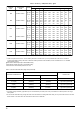
pressure. The furnace airflow rates are provided in Table2-AIR
DELIVERY -CFM (Without Filter).
When a furnace is installed so that the supply ducts carry air
circulated by the furnace to areas outside the space containing the
furnace, the return air shall also be handled by duct(s) sealed to the
furnace casing and terminating outside the space containing the
furnace.
Secure ductwork with proper fasteners for type of ductwork used.
Seal supply and return-duct connections to furnace with code
approved tape or duct sealer.
NOTE: Flexible connections should be used between ductwork and
furnace to prevent transmission of vibration. Ductwork passing
through unconditioned space should be insulated and sealed to
enhance system performance. When air conditioning is used, a
vapor barrier is recommended.
Maintain a I-in. (25 mm) clearance from combustible materials to
supply air ductwork for a distance of 36 in. (914 mm) horizontally
from the furnace. See NFPA 90B or local code for further
requirements.
Ductwork Acoustical Treatment
NOTE: Metal duct systems that do not have a 90 degree elbow and
10 ft. (3 M) of main duct to the first branch take-off may require
internal acoustical lining. As an alternative, fibrous ductwork may be
used if constructed and installed in accordance with the latest edition
of SMACNA construction standard on fibrous glass ducts. Both
acoustical lining and fibrous ductwork shall comply with NFPA 90B
as tested by UL Standard 181 for Class 1 Rigid air ducts.
Supply Air Connections
For a furnace not equipped with a cooling coil, the outlet duct shall
be provided with a removable access panel. This opening shall be
accessible when the furnace is installed and shall be of such a size
that the heat exchanger can be viewed for possible openings using
light assistance or a probe can be inserted for sampling the
airstream. The cover attachment shall prevent leaks.
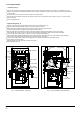
Upflow and Horizontal Furnaces
Connect supply-air duct to flanges on furnace supply-air outlet. Bend
flange upward to 90° with wide duct pliers. The supply-air duct must
be connected to ONLY the furnace supply-outlet-air duct flanges or
air conditioning coil casing (when used). DO NOT cut main furnace
casing side to attach supply air duct, humidifier, or other
accessories. All accessories MUST be connected to duct external to
furnace main casing.
NOTE: For horizontal applications, the top-most flange may be bent
past 90 degrees to allow the evaporator coil to hang on the flange
temporarily while the remaining attachment and sealing of the coil
are performed.
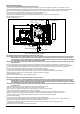
Return Air Connections
The furnace and its return air system shall be designed and installed
so that negative pressure created by the air circulating fan cannot
affect another appliance’s combustion air supply or act to mix
products of combustion with circulating air. The air circulating fan of
the furnace, if installed in an enclosure communicating with another
fuel-burning appliance not of the direct-vent type, shall be operable
only when any door or panel covering an opening in the furnace fan
compartment or in a return air plenum on ducts is in the closed
position.
Filter Type
Air velocity through throwaway filters may not exceed 300 feet per
minute (91.4m/min). All velocities over this require the use of hight
velocity filters. If a normal speed desposable filter is used and air
speed exceeds 300 feet per minute(FPM), two side returns or one
side return and the bottom return may be needed. For airflow, refer to
Table 2.
If disposable filters are used air throw away passage through filters
should be increased to twice the size of original air opening by using
a transition duct or using two filters in V shap in normal duct size.
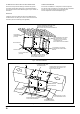
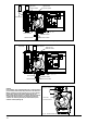
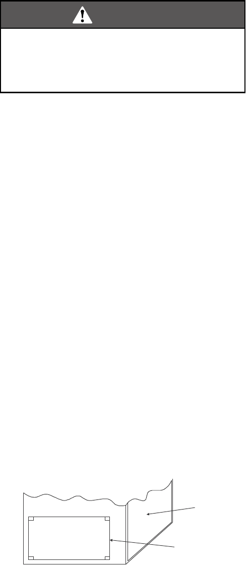
Locate the 4 cutout locations. These indicate the size of the cut-out
to be made in the furnace side panel. Refer to Fig 17, "Side Return
Cutout Markings".
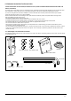
Install the side filter rack followi ng the instructions provided with that
accessory. If a filter(s) is provided at another location in the return air
system, the ductwork may be directly attached to the furnace side
panel.
IMPORTANT:
Some accessories such as electronic air cleaners and
pleated media may require a larger side opening. Follow the instruc-
tions supplied with that accessory for side opening requirements.
Fig. 17 Side Return Cutout Markings
Front of
Furnace
Corner
Markings
Side Return
One of the most common causes of a problem in furnace is a blocked
or dirty filter. The filter must be inspected monthy for dirt accumulation
and replace it if neccessarily.
Filter Size
See recommended filter size and type in Table 3.
Filter Installation
All applications require the use of a field installed filter. All filters and
mounting provision must be field supplied.
Filters must be installed external to the furnace cabinet. DO NOT
attempt to install filters inside the furnace.
NOTE: Single side return above 1800 CFM is approved as long as the
filter velocity does not exceed filter manufacturer’s recommendation
and a transition is used to allow use on a 20x25 filter.
General Requirements
The duct system should be designed and sized according to accepted
national standards such as those published by: Air Conditioning
Contractors Association (ACCA), Sheet Metal and Air Conditioning