
Installation Guide
14
I&O manual
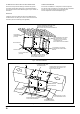
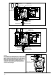
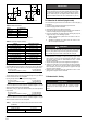
Fig. 14 - Horizontal Left Side Installation, Vent Through Top Panel
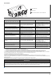
Fig. 15 - Horizontal Left Side Installation, Vent Through Side Panel
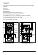
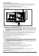
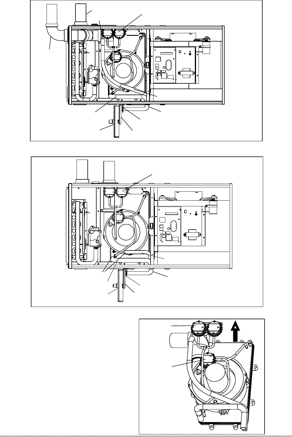
Fig. 16 - Pressure Switch Positon
upright
VENT OUTLET
AIR INLET
HOSE CLAMP
HOSE CLAMP
16mm HOSE
DRAIN TRAP
DRAIN TRAP FIXING
14mm HOSE
VENT OUTLET
AIR INLET
HOSE CLAMP
HOSE CLAMP
16mm HOSE
DRAIN TRAP
DRAIN TRAP FIXING
14mm HOSE
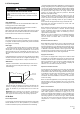
CAUTION:
In this installation, hoses connecting between ports of overflow protection
pressure switch (overflow switch) and pressure tabs on the collector box
MUST be switched. The overflow switch has two ports, which is different
from two other regular pressure switches that have only one port.
Make sure that black port (positive) is connected to the lower position tap
on condensate collector box and gray port (negative) to higher tap of
condensate box. Connecting incorrectly will result in failure to protect
condensate overflow.(See Fig. 16)
Over Flow
Pressure Switch
High/Low Fire
Pressure Switch
High/Low Fire
Pressure Switch
High/Low Fire
Pressure Switch
14/16mm Tube
14/16mm Tube