
Installation Guide
13
I&O manual
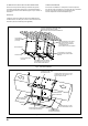
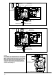
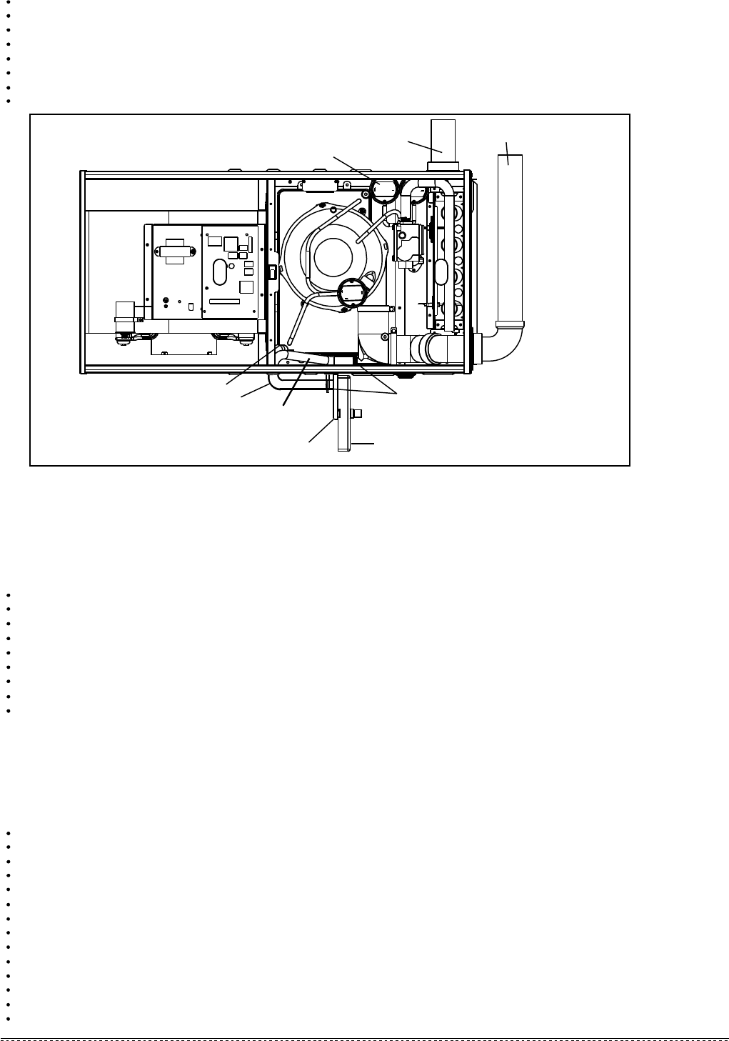
Fig. 13 - Horizontal Right Side Installation
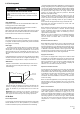
6.3.3 For Horizontal Installations
1. Air discharge to the right and vent through furnace top panel (see Fig. 13)
2. Air discharge to the left and vent through furnace top panel (see Fig.14 and Fig. 16)
Connect vent pipe and air intake pipe (if applicable) to the couplers on the furnace top panel. Use street 2 to 3” transition for 3” pipe.
Use two field supplied elbows and nipples to make flue and air intake pipes vertical. Elbows should be as close to the furnace as possible.
Use provided or field supplied (if applicable) mounting bracket to mount condensate trap on the proper location of right side panel .
Screws for mounting bracket should not interfere any components inside the furnace.
Connect 16mm hose between collector box and trap. Cut the excess hose to fit before connection..
Connect 16mm hose between collector box and trap and connect 14mm hose between inducer draining tap and trap. .
Plug both holes on rubber elbow use provided plugs. Cut the excess hoses if necessary.
Secure and tight all hoses.
Relocate junction box to the other side of cabinet if necessary.
3. Air discharge to the left and vent through furnace side panel (see Fig. 15 and Fig. 16)
Remove plug (14mm) from furnace’s right side panel and cut the insulation to the size.
Remove 3 screws securing air intake coupler on top panel and remove coupler.
Mount coupler to the right side using the same screws saved from removing top panel coupler.
Cover the top panel opening using the plug removed from side panel.
Remove 16mm knockout on right panel and cut insulation. Install rubber grommet provided in the kit bag to 16mm opening.
Remove rubber elbow connected to the inducer. Use field provided 2” plastic pipe and nipple to connect to the inducer.
Connect rubber elbow to the 2” pipe. Elbow should be connected as close to the side panel as possible.
Secure and tight all hoses.
Connect 2” pipe to the rubber elbow. If 3” pipes are used, use a field provided transition.
Use provided or field supplied (if applicable) mounting bracket to mount condensate trap on the proper location of right side panel .
Screws for mounting bracket should not interfere any components inside the furnace.
Connect 16mm hose between collector box and trap and connect 14mm hose between inducer draining tap and trap.
Cut the excess hoses if necessary.
Relocate junction box to the other side of cabinet if necessary.
Connect vent pipe and air intake pipe (if applicable) to the couplers on the furnace top panel. Use street 2 to 3” transition for 3” pipe.
Use two field supplied elbows and nipples to make flue and air intake pipes vertical. Elbows should be as close to the furnace as possible.
Use provided or field supplied (if applicable) mounting bracket to mount condensate trap to the proper location of right side panel .
Screws for mounting bracket should not interfere any components inside the furnace.
Cut and remove 1/4 inch from the end of the drain port on the rubber elbow.
Connect 16mm hose between collector box and trap and connect 14mm hose between rubber elbow and trap.
Cut the excess hoses if necessary.
Secure and tight all hoses.
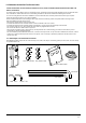
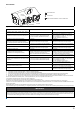
16mm HOSE
14mm HOSE
HOSE CLAMP
VENT OUTLET
AIR INLET
DRAIN TRAP
DRAIN TRAP FIXING
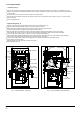
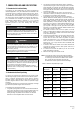
CAUTION: In this installation, hoses connecting between ports of overflow protection pressure switch (overflow switch) and pressure tabs on the collector box
MUST be switched. The overflow switch has two ports, which is different from two other regular pressure switches that have only one port. Make
sure that black port (positive) is connected to the lower position tap on condensate collector box and gray port (negative) to higher tap of condensate
box. Connecting incorrectly will result in failure to protect condensate overflow.
CAUTION: Two pressure switches (one port type switches) should be relocated to other side of furnace side panel to ensure pressure switches are above water
tap of collector box.
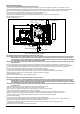
High/Low Fire
Pressure Switch
14/16mm Tube