
Installation Guide
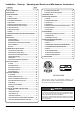
9
I&O manual
9
I&O manual
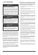
WARNING
Failure to follow this warning could result in personal injury,
death, and/or property damage.
Do not install the furnace on its back or hang furnace with
control compartment facing downward. Safety control operation
will be adversely affected. Never connect return-air ducts to the
back of the furnace.
FIRE, EXPLOSION, AND CARBON MONOXIDE
POISONING HAZARD
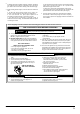
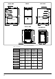
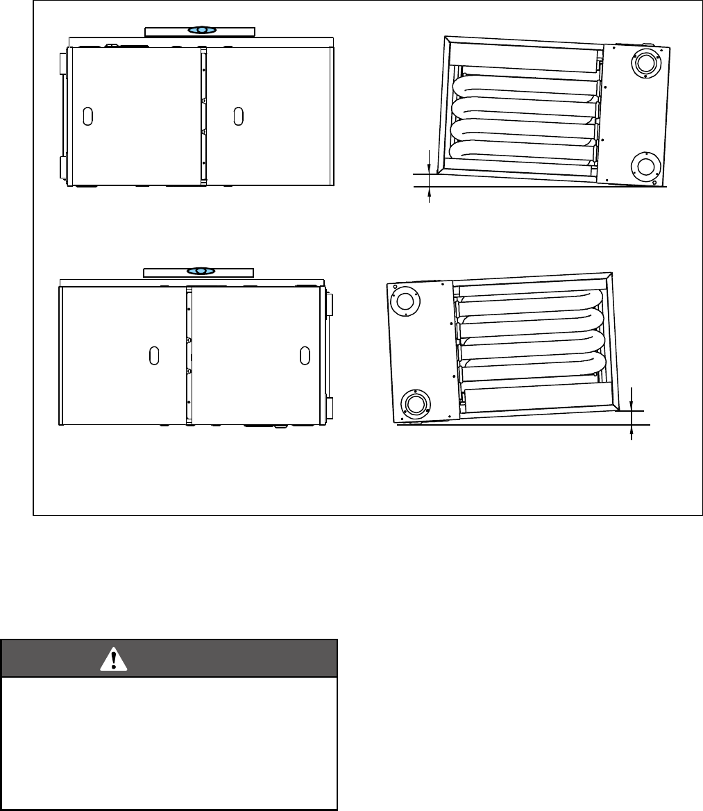
Fig. 7 - Horizontal Application-Setting Equipment
Horizontal Left Side Installation
Horizontal Right Side Installation
The furnace can be installed horizontally in an attic or crawl space
on bottom or either the left-hand (LH) or right-hand (RH) side. The
furnace can be hung from floor joists, rafters or trusses or installed
on a non-combustible platform, blocks, bricks or pad.
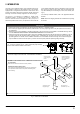
FURNACE SUSPENSION
If suspending the furnace from rafters or joists, use 3/8" threaded
rod and 2”x2”x1/8” angle iron as shown below. The length of rod
will depend on the application and the clearances necessary. (See
Fig. 8 and 9)
HORIZONTAL APPLICATIONS
Horizontal applications, in particular, may dictate many of the
installation’s specifics such as airflow direction, ductwork
connections, flue and combustion air pipe connections, etc. The
basic application of this furnace as a horizontal furnace differs only
slightly from an upright installation. When installing a furnace
horizontally, additional consideration must be given to the following:
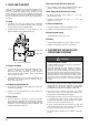
DRAIN TRAP AND LINES
In horizontal applications the condensate drain trap is secured to the
furnace side panel, suspending it below the furnace. A minimum
clearance of 7 inches below the furnace must be provided for the
drain trap. Additionally, the appropriate downward piping slope must
be maintained from the drain trap to the drain location. Refer to
Section “Condensate Drain Line & Drain Trap”. If the drain trap and
drain line will be exposed to temperatures near or below freezing,
adequate measures must be taken to prevent condensate from
freezing.
LEVELING
Leveling ensures proper condensate drainage from the heat
exchanger and induced draft blower. For proper flue pipe drainage,
the furnace must be level lengthwise from end to end. The furnace
should also have a slight tilt with the access doors downhill
((minimum 1/2"(12.7mm) to maximum of 3/4"(19mm)) from the
back panel. The slight tilt allows the heat exchanger condensate,
generated in the recuperator coil, to flow forward to the recuperator
coil front cover.
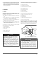
6.2 Horizontal Installation
1/2”~3/4”
1/2”~3/4”
FRONT VIEW
FRONT VIEW
SIDE VIEW
SIDE VIEW
Tilt the unit slightly (minimum 1/2"(12.7mm) to maximum of 3/4"(19mm))
from back to front to aid in the draining of the heat exchanger.