
Installation Guide

22
I&O manual
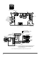
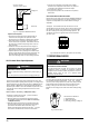
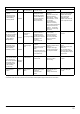
Fig.27 - Heating and Cooling Application Wiring Diagram with I-Stage Thermostat
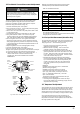
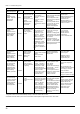
Fig. 26 - Furnace Control
Unused circulator
Unused circulator
blower terminal
blower terminal
Neutral terminal
1234
LED OPERATION &
DIAGNOSTIC LIGHT
Thermostat
IGN
N
IND
N
IND
IGN
Option
Switch
Fuse
Input voltage
115V,60Hz
Cool stage
Heat stage
EAC
Humidifier
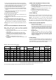
H C T I W S P I D
T E S Y R O T C A F
0 8 1 F F O F F O
0 2 1 F F O N O
0 9 N O F F O
N O N O
4 W S 3 W S
Y A L E D " F F O " T A E H
0 6
. S C E S
*
*
Option Switch Positions
115V FIELD-
SUPPLIED
DISCONNECT
J-BOX
24V
TERMINAL
BLOCK
THREE-WIRE
HEATING-ONLY
FIVE WIRE
NOTE 1
NOTE 2
FIELD-SUPPLIED
DISCONNECT
CONDENSING
UNIT
TWO
WIRE
FURNACE
C
O
N
T
R
O
L
R
G
C
W
GND
GND
FIELD 24V WIRING
FIELD 115V, 208/230V, WIRING
FACTORY 24V WIRING
FACTORY 115V WIRING
208/230V
THREE
PHASE
208/230V
SINGLE
PHASE
BLOWER DOOR
SWITCH
WHT
BLK
WHT
BLK
NOTES: Connect Y-terminal in furnace as shown for proper blower operation.
Some thermostats require a "C" terminal connection as shown.
If any of the original wire, as supplied, must be replaced, use
same type or equivalent wire.
W
GND
THERMOSTAT
TERMINALS
1.
2.
3.
R G
Y
C Y