
Troubleshooting Guide
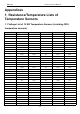

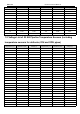
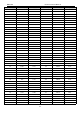
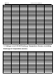

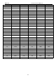

Table Of Contents
- Foreword
- Safety Notice
- CONTENTS
- Safety Notice on Maintenance
- Safety Notice on Operation
- 1. Product Introduction
- 2. Control
- 2.1 Operation Mode
- 2.2 Control Mode
- 2.3 Functions
- 2.3.1 Set Capacity Dial Code
- Set the capacity of the outdoor unit through the f
- Capacity
- 24K
- 36K
- 48K
- 60K
- Dial Codes
- 2.3.2 Set Defrost Mode
- The second digit dial code are selecting the defro
- 2.3.3 Set Operating Mode
- The third digit dial code and the fourth digit dia
- By setting the Forcible mode dial codes of the con
- Energy saving mode is achieved by setting the cond
- 2.3.4 Set Indoor Fan Speed
- Set the indoor fan speed through the four-digit di
- Capacity
- 24K indoor unit dial code
- 36K indoor unit dial code
- Level 1 (Default)
- Level 2
- Level 3
- Capacity
- 48K indoor unit dial code
- 60K indoor unit dial code
- Level 1 (Default)
- Level 2
- Level 3
- 2.3.5 Forced Defrost Control
- Press and hold "SW1" for about 5s to enter the fir
- 2.3.6 Refrigerant Recovery Control
- Press and hold "SW1" for about 5s to enter the fir
- 2.3.7 Forced Operation Control
- Press and hold "SW1" for about 5s to enter the fir
- 2.3.8 Thermostat Functions
- Thermostat model: XE70-00/E1, please refer to the
- 3.1 Wiring Diagrams
- 3.2 PCB Layout
- 3.2.2 IPM, PFC Testing Method
- 3.3 Error Code
- 3.4 Troubleshooting
- 3.4.1 “E1” Compressor High Pressure Protection
- 3.4.2 “E3” Compressor Low-pressure Protection, Ref
- 3.4.3 “E4” Compressor Air Discharge High-temperatu
- 3.4.4 “F2” Condenser Temperature Sensor Error
- 3.4.5 “F3” Outdoor Ambient Temperature Sensor Erro
- 3.4.6 “F4” Discharge Temperature Sensor Error
- 3.4.7 “F6” ODU Tube Temperature Sensor Error
- 3.4.8“EE” ODU Memory Chip Error
- 3.4.9 “H4” Overload
- 3.4.10 “H5” IPM Protection
- 3.4.11 “H6” DC Fan Error
- 3.4.12 “H7” Driver Out-of-Step Protection
- 3.4.13 “HC” PFC Protection
- 3.4.14 “Lc” Startup Failure
- 3.4.15 “P0” Driver Reset Protection
- 3.4.16 “P5” Over-Current Protection
- 3.4.17 “P6” Master Control and Driver Communicatio
- 3.4.18 “P7” Driver Module Sensor Error
- 3.4.19 “P8” Driver Module High Temperature Protec
- 3.4.20 “PA” AC Current Protection
- 3.4.21 “Pc” Driver Current Error
- 3.4.22 “PL” Bus Low-Voltage Protection
- 3.4.23 “PH” Bus High-Voltage Protection
- 3.4.24 “PU” Charge Loop Error
- 3.4.25 “ee” Drive Memory Chip Error
- 3.4.26 “e1” High Pressure Sensor Error
- 3.4.27 “C4” ODU Jumper Cap Error
- 3.5 Failures Not Caused by Errors
- 4. Maintenance
- Appendices
- 1. Resistance/Temperature Lists of Temperature Sen
- 2. Temperature/Pressure List of Refrigerant
- 3. Operation Tools

MRCOOL Universal Service Manual
109
Appendices
1. Resistance/Temperature Lists of
Temperature Sensors
1.1 Voltage List of 15 KΩ Temperature Sensors (including ODU
temperature sensors)
Temperature (℃)
Resistance (kΩ)
Voltage (V)
Temperature (℃)
Resistance (kΩ)
Voltage (V)
-20
144
0.311
71
2.523
2.825
-19
138.1
0.323
72
2.439
2.838
-18
128.6
0.345
73
2.358
2.852
-17
121.6
0.362
74
2.28
2.865
-16
115
0.381
75
2.205
2.877
-15
108.7
0.4
76
2.133
2.889
-14
102.9
0.42
77
2.064
2.901
-13
97.4
0.44
78
1.997
2.912
-12
92.22
0.462
79
1.933
2.923
-11
87.35
0.484
80
1.871
2.934
-10
82.75
0.506
81
1.811
2.945
-9
78.43
0.53
82
1.754
2.955
-8
74.35
0.554
83
1.699
2.964
-7
70.5
0.579
84
1.645
2.974
-6
66.88
0.605
85
1.594
2.983
-5
63.46
0.631
86
1.544
2.992
-4
60.23
0.658
87
1.497
3.001
-3
57.18
0.686
88
1.451
3.009
-2
54.31
0.714
89
1.408
3.017
-1
51.59
0.743
90
1.363
3.025
0
49.02
0.773
91
1.322
3.033
1
46.8
0.801
92
1.282
3.04
2
44.31
0.835
93
1.244
3.047
3
42.14
0.866
94
1.207
3.054
4
40.09
0.899
95
1.171
3.061
5
38.15
0.931
96
1.136
3.068
6
36.32
0.965
97
1.103
3.074
7
34.58
0.998
98
1.071
3.08
8
32.94
1.033
99
1.039
3.086
9
31.38
1.067
100
1.009
3.092
10
29.9
1.102
101
0.98
3.098
11
28.51
1.138
102
0.952
3.103
12
27.18
1.174
103
0.925
3.108