
Troubleshooting Guide
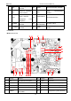
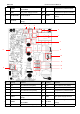
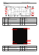


Table Of Contents
- Foreword
- Safety Notice
- CONTENTS
- Safety Notice on Maintenance
- Safety Notice on Operation
- 1. Product Introduction
- 2. Control
- 2.1 Operation Mode
- 2.2 Control Mode
- 2.3 Functions
- 2.3.1 Set Capacity Dial Code
- Set the capacity of the outdoor unit through the f
- Capacity
- 24K
- 36K
- 48K
- 60K
- Dial Codes
- 2.3.2 Set Defrost Mode
- The second digit dial code are selecting the defro
- 2.3.3 Set Operating Mode
- The third digit dial code and the fourth digit dia
- By setting the Forcible mode dial codes of the con
- Energy saving mode is achieved by setting the cond
- 2.3.4 Set Indoor Fan Speed
- Set the indoor fan speed through the four-digit di
- Capacity
- 24K indoor unit dial code
- 36K indoor unit dial code
- Level 1 (Default)
- Level 2
- Level 3
- Capacity
- 48K indoor unit dial code
- 60K indoor unit dial code
- Level 1 (Default)
- Level 2
- Level 3
- 2.3.5 Forced Defrost Control
- Press and hold "SW1" for about 5s to enter the fir
- 2.3.6 Refrigerant Recovery Control
- Press and hold "SW1" for about 5s to enter the fir
- 2.3.7 Forced Operation Control
- Press and hold "SW1" for about 5s to enter the fir
- 2.3.8 Thermostat Functions
- Thermostat model: XE70-00/E1, please refer to the
- 3.1 Wiring Diagrams
- 3.2 PCB Layout
- 3.2.2 IPM, PFC Testing Method
- 3.3 Error Code
- 3.4 Troubleshooting
- 3.4.1 “E1” Compressor High Pressure Protection
- 3.4.2 “E3” Compressor Low-pressure Protection, Ref
- 3.4.3 “E4” Compressor Air Discharge High-temperatu
- 3.4.4 “F2” Condenser Temperature Sensor Error
- 3.4.5 “F3” Outdoor Ambient Temperature Sensor Erro
- 3.4.6 “F4” Discharge Temperature Sensor Error
- 3.4.7 “F6” ODU Tube Temperature Sensor Error
- 3.4.8“EE” ODU Memory Chip Error
- 3.4.9 “H4” Overload
- 3.4.10 “H5” IPM Protection
- 3.4.11 “H6” DC Fan Error
- 3.4.12 “H7” Driver Out-of-Step Protection
- 3.4.13 “HC” PFC Protection
- 3.4.14 “Lc” Startup Failure
- 3.4.15 “P0” Driver Reset Protection
- 3.4.16 “P5” Over-Current Protection
- 3.4.17 “P6” Master Control and Driver Communicatio
- 3.4.18 “P7” Driver Module Sensor Error
- 3.4.19 “P8” Driver Module High Temperature Protec
- 3.4.20 “PA” AC Current Protection
- 3.4.21 “Pc” Driver Current Error
- 3.4.22 “PL” Bus Low-Voltage Protection
- 3.4.23 “PH” Bus High-Voltage Protection
- 3.4.24 “PU” Charge Loop Error
- 3.4.25 “ee” Drive Memory Chip Error
- 3.4.26 “e1” High Pressure Sensor Error
- 3.4.27 “C4” ODU Jumper Cap Error
- 3.5 Failures Not Caused by Errors
- 4. Maintenance
- Appendices
- 1. Resistance/Temperature Lists of Temperature Sen
- 2. Temperature/Pressure List of Refrigerant
- 3. Operation Tools

MRCOOL Universal Service Manual
19
Outdoor unit:
Model: MDUO18036、MDUO18060
Mainboard
No.
Printing
Interface
No.
Printing
Interface
1
AC-L
Live wire input
11
H-PRESS
high pressure sensor
interface
2
AC-N
Neutral wire input
12
LPP
System low pressure
protection interface
3
HEAT_TI
E_B
Chassis electric
heating belt
13
HPP
System high pressure
protection interface
4
HEAT_TI
E_C
Compressor electric
heating belt
14
T_SENSOR2
2. Outdoor tube temperature
sensor interface
4. Outdoor ambient
temperature sensor interface
6. Discharge temperature
sensor interface
5
4WAY
4-way valve
15
T_LAC
Low temperature cooling
temperature sensing